High Heat Flux Performance of Fusion Materials
|
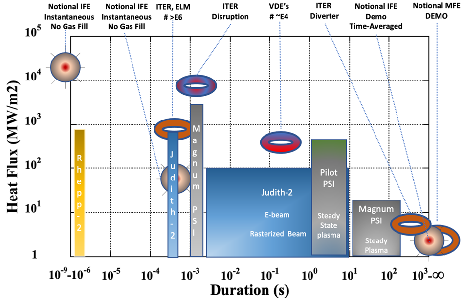
P.I.'s - Dr. David Hwang, Dr. Lance Snead, and Dr. David Sprouster The lack of HHF testing capability to support the US fusion community, whether at the coupon level required for the materials development of this proposal, or for component-level testing, has also been recognized as a serious deficiency in the wider US program by recent MFE and IFE community workshops. Historically and currently, a range of techniques have been applied to mimic the steady state heat flux of fusion power systems, or the normal and off-normal disruption events. The figure below provides a cartoon-level comparison of expected thermal heat flux for both MFE(toroidal symbols) devices and IFE(spherical symbols) devices considering the dwell-time of the heat. From this the short-duration, extremely high heat disruptions of MFE devices and the instantaneous bursts of IFE are contrasted with the lower steady state and time-averaged wall loading of ITER and assumed next-generation reactors. This figure also overlays the a representative suite of HHF test facilities with their common pulse lengths, which provide a relatively good match with the requirements, though perhaps at a somewhat lower heat flux and duration than optimal.
Figure : Wall heat flux for MFE (Toroids) and IFE (spheres) with selected capability overlays. Facility capabilities are approximate and can be tailored to achieve different experimental outcomes. Within the EMREL FACET Lab two continuous wave lasers are being applied for coupon-level HHF testing. The CW steady state laser to be utilized is an existing IPG Photonics 4KW Ytterbium CW laser capable of >20MW/m2 over >1-cm2 sample area. (accounting for W spectral reflectivity) from <1 ms to continuous operation. A range of lasers can provide appropriate power and duration (figure above) to mimic disruption events. Our HHF system however, uses a second IPG Photonics 4KW Ytterbium CW laser to provide disruptive heat fluxes of >100 MW/m2 over a reduced spot size of 0.5-cm diameter or smaller (e.g., >1 GW/m2 over a ~1.2-mm diameter spot) mainly for durations spanning from 0.5 ms to 100’s ms. |