Research Journal
This page is an attempt to describe the different projects that I worked on outside of classes. It goes into what I learned from various projects and just how my experiences with different events.
Graduate
The summer (2014) between undergrad and grad I worked in a group on creating long range bonds between Rb atoms. Beggining of 2015 I changed groups to work on studying the ultra-fast dynamics of molecules using high power LASERs. In the summer of 2015 I went on a trip to Berkeley and to Stanford for different beamtimes that our group had. On the days that I was at UCONN over that summer I helped with the assembly of the COLTRIMs system.
Undergrad
In the summer 2012 and the spring of 2013 I worked with Distinguished Professor Harold Metcalf; you can jump to those sections by clicking on their respective links. In April 2013 I presented a poster poster at URECA that aimed to outline the qualitative physics behind A.R.P. Directly below is from my work in the summer of 2013 for Micheal Rijssenbeek.
Graduate Research
Ultrafast LASERs
Summer 2015
The Cold Target Recoil Ion Momentum Spectrometer (COLTRIM) system is a unique vacuum chamber set-up that allows our group to measure coincidences of positively charged ions and negatively electrons after a fragmentation of a large molecule. When the molecule is subject to intense short pulses of radiation from the ultra-fast LASER in the lab, the molecule dissociates into fragments (atoms or small molecules) from its original form. The concentration of each time of fragment, the speed at which it hits the ion detector and the time related response on the electron detector give a lot of information about how the sample breaks apart under radiation.
Advanced Light Source at Berkeley (ALS)
Dr.Berrah’s group went to ALS to conduct two experiments; one on the molecular dynamics of C80 (a fullerene with 80 carbon atoms), one on the ionization pathways of small C-chains and -Li.
I worked on the stationary vacuum chamber studying the C-chains and -Li with Dr.Rene Bilodeau, Dr. Dan Gibson and Dr.Wes Walter. I had a shift roughly from 9am to 9pm and the three previously mentioned men with their doctorate worked staggered shifts through the 24 hour day.
The main idea was to study the way in which high energy light tore electrons off of different chains of carbon atoms and negatively charged Li. Studying the probability of ionization of the sample with respect to the intensity and energy of the photons gives an absolute cross section. A cross section acts as a representation of how a sample interacts with light or with other matter. To get a complete picture of how the sample will react to any light, a cross section must be found for each wavelength.
The light was created in intense pulses from a synchrotron. This is accomplished by creating small tight bunches of electrons that are pushed close to the speed of light and whirled around in a circle. When a charged particle changes direction it emits radiation dependant upon it’s acceleration. The electrons moving close to the speed of light accelerate very fast as they turn in a circle. A window is placed on the electron ring that lets out this radiation. Since the electrons are in bunches, each bunch produces it’s own burst of photons; this is why the pulses are separated.
The area where the sample was created is called the oven. A safety-locked faraday cage sealed off the incredibly large voltage and current that was used to push the charged particles out of the oven towards the rest of the apparatus. We used a Cs sputter source that ionized Cs atoms to be used as a tool for creating a gassious sample. The Cs ions were shot toward a pure solid sample of carbon. Some of the carbon atoms were broken off from the impact. Of the carbon atoms broken off, some of the were negatively charged and therefore attracted away from the sample by electrically charged metal (electrostatic plates).
An einzel lens is a series of electrostatic plates used to create a gradient electric field that focuses and directs the charged particles along the a desired trajectory. A mass analysing magnet was used to isolate the sample from the contamination in the vacuum that the various vacuum pumps had not picked up. Every part of the apparatus (the Cs sputter source, electrostatic plates, einzel lenses, mass analysing magnet, diffraction grating for light) had to be carefully calibrated for each sample.
The negatively charged sample then passed through the interaction region where it was irradiated by photons from the synchrotron source. These stripped off electrons and the last of the electrostatic plates selected the desired ions to pass up to the particle detector (CEM).
I was in charge of aiding with the calibration for new samples and for creating the plots of data taken during my shift. I created organized pdf’s based on the different ions and pathways to show patterns. Normalizations for subtracting background, fluctuations in the beamline intensity, changes in density of gaseous sample, and the non-linear response of the photo-diode. These adjustments along with the calibration of the diffraction grating and the exact electron response of the detector gave plots of absolute cross section. I had enough information to be able to get the relative cross section immediate after taking the data so that decisions about what parameters to change or what pathway to move on to could be made in the moment.
The samples could either have been of carbon or of lithium. The lithium samples were of
taking electrons off of negatively charged Li. The carbon chain could be any combination of
two, three .. eight carbon atoms. The pathway of an interaction is the specific product and
result. If two positively charged carbon atoms (+C_2) results in one negatively charged
carbon atom(-C), then that would be one pathway. (+C_8) -> (-C_2) would be another pathway.
I have to give credit also to the three undergraduates from Denison College and Dr.Gibson
son who all made the atmosphere more fun to to be in and made clear contributions to the
success of the experiment.
Linac Coherent Light Source at Stanford (LCLS)
From July 14th to the 22nd we went to a free electron LASER source at stanford university’s campus. The principle investigator of this project was Dr.Markus Guehr. Our group was there as collaborators to help out with the real time analysis of the data. My friend Razib Obaid and I were there on the day and night shift respectively. I shadowed Adi Natan, Thomas wolf, and Andrea Battistoni while they wrote code to add necessary corrections so that the code could be understood. There were huge amounts of data coming in; which meant that it needed to be truncated, cut, filtered and adjusted before it could be useful.
Thymine is part of the nucleobases that forms your DNA. Skin cancer can be formed when thymine is excited by ultraviolet light. When ultraviolet light ionizes thymine it can cause a mutation in the DNA chain connecting two thymine molecules together to create a thymine dimer. Studying auger decay in thymine with a free electron laser allows us to graph a relationship between the absorption rate of thymine across a span of ultraviolet light; giving us information about how the molecule was ionized and the dimer was created.
Charged particles create radiation when accelerated. The free electron LASER sends bunches of electrons down the SLAC beamline at close to light speed. These electron bunches pass through undulators that use static electric fields with periodic maxima and minima for the length of the undulator. The electrons follow the push of the field and are wiggled up and down. This uniform movement causes all the electrons to create and self-stimulate radiation at the same wavelength. The bunch has passed through an undulator of a set length and generated a pulse of light from its motion inside the magnetic field. Later down the beamline the electrons are pushed to the side into a beam-dump so that they don’t propagate down the beamline to the target.
There were a lot of built in tricks in python that allowed them to perform these adjustments to the data with one line coding that I hadn’t seen before. My intuition now is to always look for pre-written functions to call to execute whatever task you are trying to code. The built in functions have been defined by someone who spent hour upon hours of their time making it that one code efficient, there is no use trying to compete with that when you have your own job to do.
Dr.Guehr was a great PI. He cultivated this atmosphere by example of incredible passion and excitement. There was more than one time when everyone in the room started yelling, cheering at the screen as a plot went up to show how well the last run had gone. I wasn’t on the project from its start and I didn’t pretend to understand the excitement, but I did love to be surrounded by passionate people.
One of my fellow graduate students gave a 5 minute talk on successful physicists. His main point was their unrelenting passion for their work. I’ve always loved this about physics. Most people that study physics are really passionate about it. I intend on never losing passion for my work; that is why when I ask myself where I want to apply my physics knowledge, I realize that I could aid the diagnosis and treatment of deadly diseases by working on medical devices that rely on complex physics.
Additional thanks to Jakob Grilj, Melanie Mucke, Nora Berrah, Timur Y Osipov, Phil Bucksbaum, Thomas Wolf, James P. Cryan, Kelly J. Gaffney, Stefan P, Moeller for aiding to the atmosphere and inviting us to help.
Spring 2015
In January 2015, the group spent a large amount of time researching papers independantly and sharing them at our meetings. I really like the dynamic of group meetings. Filling our group meetings with presentations was a nice way to learn about new papers while we waited for equipment necessary for our research. We spent weeks helping Soroush and Razib prepare for their oral presentations. It can be difficult on both sides to take and receive criticism, but it is good practice for all of us; being direct and transparent is always a good way to communicate.
The paper I presented was ‘Direct Determination of Absolute Molecular Stereochemistry in Gas Phase by Coulomb Explosion Imaging’. I easily spent a couple days before the semester started just preparing for this. There are so many unknown words in every paper that it is always difficult to follow what is being said. Finally being able to understand the paper after so much work was wonderful. Such a sense of pride in being able to understand a paper on a subject that I haven’t previously studied.
Ultra-Cold Molecules
I spent the summer before my first semester with Ryan Corolla and Micheal Cantara in Dr.Stwalley’s lab. There was a group dynamic that I hadn’t been exposed to before. All aspects of the experiment were regularly discussed by all members. It was good to see what kinds of problems arise on a regular basis from a working experiment, and how there is always an inefficient way of doing things and an efficient one.
Jen Carini came in one day to help with a computer problem that we were having. She knew a command sequence to push on the keyboard that caused a forced reboot to the system. Without this little trick we would have been stuck in the same circle we were in. I keep seeing a bunch of little tricks like this that can really save hours of work in lab.
I picked up a grasp of the layout of lab and was able to do things like turning on the equipment in the morning, making a mot and locking the LASER. We also spent a good amount of time debugging a YAG amplifier, before calling in a service tech to fix it.
Dr.Stwalley’s lab had a lot of different parts to the system. There were two Ti:Saphire ring LASERs, one fed by an Ar and the other fed by a Verdi LASER. The ‘Verdi fed’ Ti:Saphire was directed into the vacuum chamber for excitation of the Rb atoms from the 5s state to the 5p state. Once some of the Rb atoms were in the 5p state, they would feel an attractive potential from the Rb 5s atoms and form a trilobite-like molecule.
The ‘Ar fed’ Ti:Saphire was sent through high power rated steel fibers to a ‘home built’ amplifier system comprised of dye cells. A Nd: YAG LASER also pumped the same dye amplifier. The output of this was focused into a frequency doubler to take the green light to UV. The UV light was then directed into the vacuum chamber for excitation of the trilobite-like molecules.
Immediately adjacent to the vacuum system was a master-slave LASER system with Saturated Absorption Spectroscopy (SASpec) and an Acoustic Optical Modulator that was all responsible for trapping the Rb molecules in a small gas cloud in the center of the vacuum chamber. I wrote a bit about the concept of LASER cooling in undergrad and it can be found online. http://hyperphysics.phy-astr.gsu.edu/hbase/optmod/lascool.html
It was a great experience overall. The mere fact of being on campus a summer early was nice to get to know the area and the department. I enjoyed meeting a good amount of the people before the semester started. It also gave me a great opportunity to meet the other professors in AMO at UCONN.
Undergraduate Research
Summer 2013
Wednesday, July 31th 2013
I’m quite happy with the way the code is coming along. I am so close to actually implementing physics. The files are a bit of a mess and the comments need to be edited, but it compiles and spits out hits on the detector. The code for tracking the photon tphoton doesn’t seem to be set up properly to actually do anything yet. There will have to be a lot of debugging done tomorrow!
Thursday, July 25th 2013
After fixing all the weird things that went wrong during the installation of GEANT4, I was able to start running the examples that came with the installation. Every time I tried to take a step forward, something went wrong and I had to spend hours looking through all the documentation I could find and then just searching the exact error message I would receive. I got a lot of them working, but was only able to do minimal things like create geometry and the define number of runs. I used a HepRApp visualizer to see the output and got some pretty pictures, but couldn't find a thorough explanation as to what was physically going on. Most of my time was spent trying to figure out what exact syntax I needed to do the next step. I felt like I hadn't done physics or learned anything in weeks.
I decided to just give up on GEANT4 and ROOT entirely. I had nothing to show for two months of work, it wasn't a productive way to learn or create anything useful. Instead I thought I would attempt to carry out the initial plan but program everything in C++ myself. I started earlier this week and have a collection of files visible at the bottom of my programs page. I also uploaded a picture of one of the GEANT4 example files I was able to get running.
Wednesday, July 10th 2013
I was looking up the decay of a free neutron and realized that its mean lifetime is on the order of a 500 s. The proton on the other hand has a predicted mean lifetime of 1036s ! I realize the theory behind the lifetime of a proton isn’t perfectly understood, but this is an incredible difference. They aren’t even remotely on the same order of magnitude. In volume I of the Feynman Lectures on Physics fig. 7-14 he gives the ratio of Electrical Repulsion to Gravitation Attraction on the order of 1042; not to imply any connection, just to try to point out another example in physics where the order of magnitude of two qualitatively like things are orders of magnitude apart.
Monday, July 8th 2013
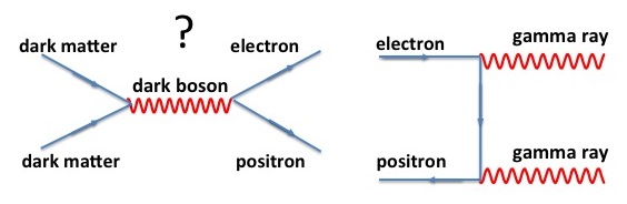
A friend posted a link to a blogging website called Quantum Diaries. It was a dark matter blog by Pauline Gagnon that was a very interesting read for those that haven’t studied the subject. The main reason I am bring it up is because It appeared to me that the feynman diagram had the arrow for a positron going in the wrong direction. I could be wrong about this, and even if I’ve correct I’m just nitpicking. So I thought I would comment on it in the hope that I understand these diagrams well enough to notice errors in convention.
Monday, July 1st 2013
I'm not sure if it is because there is something I am missing or if I just need to run through the practice examples in A First Course in General Relativity, but I am really not comfortable with natural units. 1 second = 1⁄3*10-8 *m = 2.0*10-7eV*m*s The idea of setting these units equal to each other just seems wrong.
For a while I didn’t understand how to interpret Feynman diagrams like the
one shown below on the left. After watching a
Feynman lecture
I realize that my problem of understanding was with the use of anti-matter
moving backwards in time.
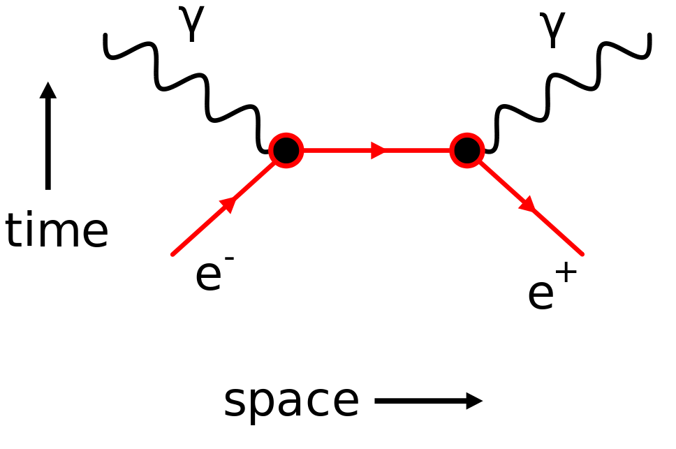
The image on the left shows an electron - positron annihilation producing two gamma rays. The electron is shown to move forward in time and towards the positron in space. The position moves from the point of interaction backwards in time in a direction farther away from the electron.
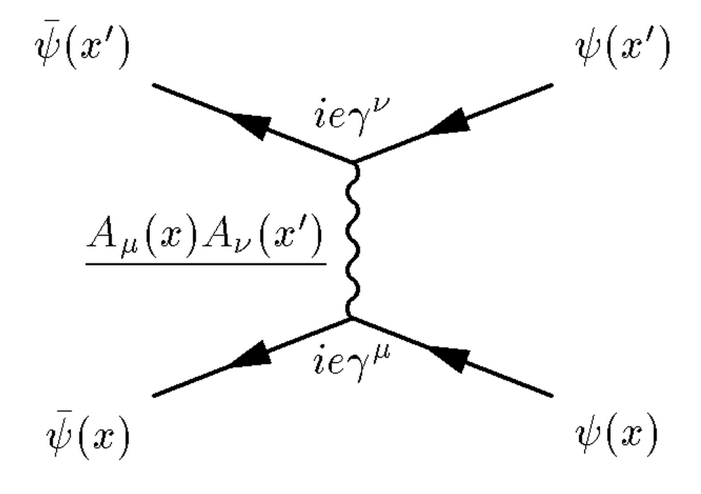
The image on the right shows a generic Feynman diagram to help one’s understanding of how the diagrams in general relate to Quantum Mechanics.
Monday, June 24th 2013
I finally feel like I got something accomplished. My work has been frustratingly unsuccessful until this point; even now I’m not too proud of it. I understood how to use TLorentzVector well enough to do something with it and have been playing around with different ways that may be important to manipulate vectors.
Thursday, June 20th 2013
I had hit a wall the day before and had not received a reply from my advisor so I
spent the day reading.
Author: Amos Emerson Dolbear
Title: Matter, Ether and Motion Rev. ed., enl. The Factors and Relations
of
Physical Science
Ebook # 31428
I read a good bit of the first section on matter which was really entertaining in
the first couple pages in its approach to explain how early scientists defined
matter. The approach was very philosophical, which seemed to be the basis of the
author’s claims. There was also a lot of elementary physics that seemed to add no
more than fluff to the rest of the chapter. The struggle here to define matter and
thereby differentiate it from other things in existence and question what we call
space is really entertaining with our current standard model of physics. Our
curiosity has driven us to a point where the standard model has such sharp
distinctions between different forms of existence and interaction that it is
helpful to attempt to define the only thing (matter) that interacts with our brain
and therefore perception of reality.
Author: P.A.M. Dirac
Title: Quantised Singularities in the Electromagnetic Field
Recieved: May 29 1931
If physics can be defined as the study of everything that exists, then we can
define math as humans’ attempt to precisely and consistently describe physics. This
statement is easily acceptable for early societies where math consisted of counting
and drawing the basic structures of things observed, but it causes many problems
for students as they learn to accept the abstract nature of modern day math. The
first problem with many students is imaginary numbers; the idea that making up a
value with no correlation to reality to find a solution to an equation would ever
be useful in physics. As every second year student knows and grudgingly accepts,
imaginary numbers are a fundamental part of modern physics. Dirac discusses a
problem encountered regarding an electron having negative kinetic energy. The
reader eventually noticing that he is referring to a positron (well accepted
anti-particle of the electron) realizes how human intuition can’t be trusted to set
the boundaries of mathematics.
The rest of his paper I read was very dense and I cannot summarize any of it just
yet.
Spent a good bit of the day trying to figure out how to use tex studios. In PHY 277 it was so much simpler to simply write in a text editor and then run a compiler in a terminal; I may go back to that
Friday, June 7th to Wednesday, June 19th 2013
- Wednesday: Spent large part of the day fighting with different functions (TLorentzVector TVector3), and trying to understand what #include statements to declare.
- Tuesday: Is there a function I can call for Cherenkov radiation? How do I define the geometry of the LBar? How to I initialize and update the LorentzVector?
- Friday: Rasmus directed me to an actual tutorial that showed you how to get started with ROOT. Monday: It seems i spent the entire day working through parts [Using TTree::Draw() to access a TTree, TTree and Its Data, Using a Macro to Read a TTree, Histogramming]. 6 of 13 left
- Thursday: Most of the day was spent trying to learn from files that were marked under a directory called tutorials. The only contents of the files were examples that could be executed, so after hours of pouring through them I still didn’t understand how to write a macro of my own.
-
Wednesday: Hal gave a talk on superposition that was made to be the first of a
series of lectures leading up to a brief qualitative understanding of entanglement.
It was really cool to hear a description of features of quantum mechanics and to be
able to guess what the corresponding mathematical basis was based on material from
PHY 308:Quantum Mechanics.
At three I again attended my last group meeting so that we could celebrate Hal’s birthday. I may have never been as enthusiastic about European culture as my mother, but Hal’s preference of pounds of strawberries and whip cream over a traditional cake is a fantastic idea. - Tuesday: I have been looking through some kind of tutorial trying to get used to using ROOT. I need to look into electromagnetic particle shower and askaryan effect to see if they may be relevant to my code. I compiled a list of equations to use for the Cherenkov radiation, but it is really hard to know if these can be used since they were derived under the assumption of certain conditions that I don’t think will be applicable for ATLAS.
- Friday, June 7th to Wednesday, June 19th Friday: Dean set me up with an account on Stony Brook’s cluster so that I can have remote access to ROOT.
Wednesday, June 5th 2013
I had worked for a while on a code
that was able to bounce around a sphere in a closed container. I was under the impression that this
was the kind of thing I was
going to be spending the next couple weeks working on and was proud of what it could
do despite its bugs.
Arriving wednesday I learned that I was going to be using ROOT instead. At least I
remember the basics of programming now.
Sunday, June 2nd 2013
Before leaving for the semester I had asked for a little direction as to where my time
would be best spent in preparation for this summer’s work. Professor Rijssenbeek gave
me a task to simulate the motion of a ‘photon’ traveling through a piece of quartz
used to guide the photon to a detector for a reiman pot model. I was really excited to
start writing the code, but had to learn the basics of the language first. He also
sent me a pdf a couple days later that I was to thoroughly study.
I can unfortunately say that I have not accomplished either task. Python is a higher
level language than I am used to, and it is taking some time to get used to the
differences. The pdf simply had a lot of information I am unfamiliar with, and I would
just need to keep walking through it; looking things up as I move along.
Spring 2013
To jump to Harold Metcalf's Research Group webpage
Monday, 6th May 2013
Chris was running his experiment today. He was looking at the RF signal going to a linear db amplifier that was part of his SAS spec set-up. The power output was significantly low so he opened the amplifier to check for broken fuses. All the fuses found were checked with a multimeter and seemed to be working.
The two rows of total 24 glass tubes are old vacuum transistors.
The black box second from the left appears to be an AC to DC converter.
The black box to its right is the main part that amplifies the signal.
With the lights turned off and a LASER thermometer we inspected what we could about the amplifier while knowing almost nothing of how it works. We could observe that two lights in one row were lit while only two lights in the other row weren't lit, and the different temperature readings of the tubes corresponded to these same differences.
Friday, 3rd May 2013
There was a fifty percent loss of light that was traced to a fiber coupler before the
five watt amplifier. When the fiber is pushed into the fiberscope the ceramic end of
the fiber can rotate if the fiber is pushed too far. To re-align the beam so that it
can pass from one fiber to the next, the ceramic end was rotated to look for an
optimal position. In doing so the tip of the ceramic cam out?!
Further work was put off until ThorLabs could be contacted about the problem. A couple
days later a generic useless response was received, and work started again hoping the
problem wouldn’t arise again.
Monday, 29th April 2013
A filter was placed in the beam line to clean up the ‘frequency of the pulse’ . the power was significantly reduced; so the pulse generator was set at max output, and an rf amplifier was placed after it and before the pulses were split into the two beams lines.
Monday, 24th April 2013
URECA poster presentations were today in the SAC ballroom. It was great to attempt to explain what A.R.P. is to people that haven't spent as much time in AMO. I didn't have to explain what it was to any non-science students, but I have had plenty of practice with that between my friends and family.
Even more so, I enjoyed walking around and talking to other people about their poster. I wasn't rude, but asking them difficult questions about things they didn't comfortably understand was fun since I knew excatly how they felt. There was one poster in particular that I didn't understand. It was made by an English major on some kind of poetry. I truly didn't understand the basic parts of her research from her poster. After talking to the student for some time, I learned what her motivation was, but she stated that there was no way to difinitvely test her hypothesis. As one would expect, there would be no achievable way to disect and reproduce art in some standardized way devoid of any muse; like assembling a shelf.
Monday, 15th April 2013
Today John showed me how to replace the tip of a fiber. Another process that’s simpler and more hands on than expected. We had to strip the casing, the buffer , and the fiber caddling to get down to the bare fiber. The casing was soaked in isopropyl alcohol and so was the fiber. After soaking, the metal casing is held up to the light to make sure there isn’t any dirt lodged in the path of the fiber. The fiber was then pushed through before the apoxy is mixed to ensure again that it would pass unobstructed through the metal casing. Then filled the casing with apoxy, stuck the fiber back in, crimped the metal jacket and push on the plastic jacket.
Thursday, 11th April 2013
John has one beam line turned off and is walking around fiddling with different things to see what will cause a stronger push from the other line. The line that is present is reflected back through the vacuum chamber to act as a second beam with equivalent characteristics. The phosphor screen shows a push, but not want is expected. We were able to observe that there was too much cw light, but when a solution was approached there wasn’t enough power reaching the amplifier for it to work.
Thursday, 28th March 2013
There was a noticeable push on the atoms, but the direction didn’t
correspond to the delay times that were calculated. So we were
experimenting with different lengths along the beam line to see directly
what made the delay worse or better. With each new length of the beam
line, we got a better feel for the correlation between the length of the
line and delay of the pulses.
Its nice to see myself getting more comfortable with each different piece
of equipment: for locking LASER frequency, lighting and purging the
source, and all the little tricks to maximize light into a fiber. I’m
being expected to do more each day, its great!
Wednesday, 27th March 2013
In group meeting there was a long discussion about the approach Yuon was using as he scanned for Rydberg states. I couldn’t understand what the competing ideas were, but at one point I picked up something about extending the size of the bin to pick up more Rydberg states. Chris suggested that he could use the scope to integrate over the potential to ‘count’ all the different Rydbergs.
Thursday, 14th March 2013
The phosphor screen randomly blew while John was in the lab. He heard a loud sizzle/crack, checked inside the vacuum tube, and found the mcp and phosphor screen had burn marks on them. The phosphor screen has two metal plates on either side with a large potential jumping from one to the other. If there is even a small bump on one of the plates, the electricity will arc from that point to other plate and burn the screen in between. He proposed the idea opportunity for me or James Dragan to learn how to replace the tip of a fiber.
Wednesday, 6th March 2013
The fiber worked after the fix, but the BOA blew out a different connecting fiber. This fiber was fixed, but the set up was not put back together out of fear of the fiber blowing as had happened previously this semester. A new BOA was ordered and is suppose to arrive in about a week.
Monday, 4th March 2013
The waveguide on the amplitude modulator in John’s set up only accepts certain polarizations. There was a burn mark on the fiber leading into the amplitude modulator that was causing a drastic interference pattern in the beam, such that a significant percentage of the light was not entering the amplitude modulator. The pattern made on the IR card had a time dependence which is not something that could be explained by the damage done to the end of the fiber, but after the tip of the fiber was polished, there were no more problems measuring stable power output from the fiber. The glowing area on the IR card resembled a gaussian beam, and James Dragan was left to learn how to adjust the polarization paddles, then to couple the light further down the beam line into a different fiber.
It was really interesting to see how to polish the tip of the fiber. The process was relatively simple. The machine that the fiber was locked into basically just sanded the tip until the burnt tip was gone. I had expected there to be a lot more meticulous hands on work. The machine simply moved a coarse material in circles on the tip of the fiber, then John had to lift the fiber and move it to the material that was more fine grained.
Friday, 28th February 2013
Chris was fixing the cat’s eye set up he was putting for future convenience in the beam line. The best way I can describe a cats eye set-up is that it is a nifty trick. A cats eye is build as such: a beam is coming in from the right into a concave lense that focuses the beam down to a point on the mirror. The beam is reflected back into the lense and continues in the direction it came as a beam roughly collimated with the beam size/shape it had before it hit the lense. Now you see why I refer to it as a nifty trick, because it is so simple but so clever.
The first cat’s eye put in wasn’t giving Chris the proper beam shape that he desired, so he used a lense with a smaller focal length. The smaller focal length meant that the fixed distance between lense and mirror would have a larger percent error for the same ‘amount’ of human error. To get more precision, the mirror and lense were mounted on a small translational stage. The stage could be moved as a single entity; keeping the separation in the cat’s eye constant, and allowing for movement back and forth on the beamline.
The light left a fiber, reflected off of a polarizing beam splitter, traveled into the cat’s eye, and then back into the beam splitter (passing through this time). The focal length and distance form the beam splitter were chosen so that two points along the line, equidistant from the beam splitter, would have equivalent size/shape. Measurements showed that there was an acceptable error of just under 10%.
Tuesday, 19th February 2013
John was able to observe the light on the atom’s beam line in the morning, but the liquid nitrogen tank ran dry before the afternoon was over. We spend the time without atoms looking at the pulse delays of the two beams. I was very surprised to learn that one can measure the nanoscale pulse delays by using a ruler to compare the distance down to a millimeter difference in beam paths to the atoms. I wouldn’t have expected that a human could measure something so fast, but the math doesn’t lie. The time delay between peaks of the pulses was about 6 ns, twice the delay desired. The pulse itself is 3.125 ns, and to have the pulses successive the time delay between the pulses needed to be cut in half. This change corresponded to a movement of about 18 inches in one of the beam lines. Mirrors were moved, a new lense was chosen, and I got the chance to remember how to walk a beam back into a fiber so that we could make this adjustment in the beam line. The end result on the detector was that the pulses were about seven nanoseconds apart, but one beam line had four nanoseconds farther to travel before they both hit the atoms. With this in consideration the actual delay between the pulses was really close to the desired : 3.2 ns. An improvement could be made to get the pulse delay closer to 3.125 ns, but this small of an error wouldn’t have a substantial effect on John’s ability to observe ARP forces at a later date.
Sidenote: It is great to have been around long enough, and to have taken enough course in physics to understand the things the graduate students and professors say. A year ago, listeing in on the group meetings sounded like trying to understand spanglish; only catching every other word and inferreing the rest.
Monday, 18th February 2013
The data taken along with the observations of the vertical interference patterns looked good. A gaussian fit was made to all the data points taken for the power meter with a micron slit on a translational stage, and the beam stayed collimated with a reasonable error. What has to be done now that the beam profiles were as hoped, move on to worrying about the pulses and phase of the light striking the atoms.
Chris was running in the lab so I stayed and helped him with what I could as John went over some of the data he had. I got a refresher on Chris’s lock set up, he showed me the beam path and reminded me what it entails to lock the beam in his setup. We spent some time taking different sets of data; each with adjusted detuning and a different combination of the two beams, every combination had hundreds of pictures averaged to represent it, and a background image to be used as a reference frame for the peaks. Each set of these different combinations had a different associated magnetic field - increasing in even amounts. Then, as I was leaving, Chris changed the direction of current through the helmholtz coils and the process was repeated. The earth induces a magnetic field that is always present and static, so it should have a noticeable different effect on the first series of sets than the second series. One series of sets should have a magnetic field that interferes destructively and the other constructively. As far as the atoms are concerned, the direction of polarization of them isn’t important as long as it is along a certain axis. Looking at the two sets of data should divulge a lot about the effects of the earth’s magnetic field on this experiment.
Friday, 15th February 2013
Friday, Marty advised that glass be placed at the end of the path so that we could observe the interference pattern created. The glass didn’t have a back and the interference pattern was created from the reflection of the light directly off the front of the glass and of the beam reflecting off the back of the glass. The single beam split into two and overlapped creating a vertical fringe pattern that was used to be used to judge the collimation.
A final attempt was made to use the power meter before the days end, and it was discovered that the cord connecting to the power meter was ripped exposing the wire. It was really cool to watch John makeshift a fix.
Thursday, 14th February 2013
A lense needed to be found that could be placed at the available spots along the path to get the desire ~ 5.5 mm circular beam. The much more basic method of taking data points with a power meter on a transverse micrometer stage was also used to study some of the beam paths.
Question: In Electrodynamics II I noticed something that bothered about electromagnetic waves. All waves on the electromagnetic spectrum travel at the same speed in a vacuum. The energy of the wave is associated with the frequency or wavelength. In addition to this parameter, an amplitude term was written on the board for a specific propagating wave. If greater energy is associated with greater frequencies, then what is greater amplitude associated with. It is well understood that the interaction between matter and an EM wave is directly related to frequency of the wave; e.g. the photoelectric effect only works for certain frequencies. The professor of the class didnt want to come out with a strong answer on the spot, but what I gathered is that the increase of amplitude can be seen as increase intensity of the light.
Week of February 4th to 11th, 2013
The past two weeks have been spent using a beam profiler to study the last part of the beam going into the vacuum tube. A lense needed to be found that could be placed at the available spots along the path to get the desire ~ 5.5 mm circular beam. The much more basic method of taking data points with a power meter on a transverse micrometer stage was also used to study some of the beam paths.
Summer 2012
To jump to Harold Metcalf's Research Group webpage
Week of 8/20 --> 8/24 2012
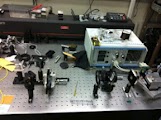
Diode LASER Project
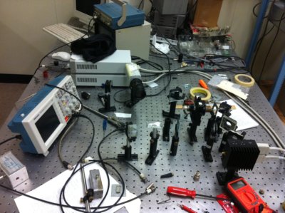 Click Here to see more pictures of the
equiptment
Click Here to see more pictures of the
equiptment
This is the basic outline we used to plan for the different problems we may encounter with fixing the LASER.
James Dragan and I worked on measuring the linewidth of a LASER diode. We were told by Hal that the linewidth wasn't small enough to make out the hyperfine states of Rubidium. Our job was to investigate into this problem and then fix the problem if there is one.
Fixing Grad Lab’s Diode LASER for Saturated Spectroscopy of Rubidium
Ultimate Goal: Get linewidth observed from Fabry-Perot to 3 or 4 MHz
Plan of Attack:
- Fire up Thorlabs LASER
- Find resonance (luminescence in Rubidium cell)
- Look at width in Fabry-Perot
- Look up Diode Current Controller Manual to find switch for positive or negative current. Then look at each other diodes manual to find their associated anode-cathode setup. If the diode cap is NOT clipped:
- Replace existing diodes with alternative ones
- Find resonance
- Look at linewidth from Fabry-Perot
- Make plans for creating a mount
- Talk to Hal at this step
- Draw up plans
- Give to machine shop to build
- Take diode from Thorlabs mount and put it in the Sacher LASER
- Switch diode to new cavity
- Find resonance
- Look at width in Fabry-Perot
	Outcomes:
		Width is same: problem with the diode
		Width is smaller
			Small enough: problem with Thorlabs, but finished
			Not small enough: combined problem of diode and mount
		Width is larger:
			Problem with Sacher LASER
			Inconclusive on diode
The actual testing with the LASER
Getting Started
Before this week, I had never experienced working with a diode LASER in this way. The only one I had used had a single piece of electronics that was preset for the LASER, and I never touched any of the knobs. When I arrived on Monday, I was alone with the LASER after a brief lecture on the theory of diode LASERs. I had an idea that there was a max current that would burn out the LASER, and that the Rubidium cell would only fluoresce with the right temperature and current combination.
I spent a while looking around reading everything that seemed relevant, I finally took a leap and turned on the current and temperature control for the LASER. I didn’t have a good idea of the threshold current and didn’t even approach 40 mA out of fear blowing the LASER. I spent some time with the lights off looking at the difference between the LASER with some current and the emission after the threshold current (34 ± 0.1 mA) was reached.
Finding Fluorescence
I asked for help from Hal and fluorescence was achieved in the Rubidium cell; observed with a CCD camera. The exact current required for fluorescence varied every time the setup was turned on and off, but a tenth of temperature deviation from 25.75 (degrees Celsius) largely altered the current needed for fluorescence. A photodiode was set up behind the Rubidium cell and connected to the oscilloscope along with the current controller. James Dragan and I spent a long time learning how to use all the different features of the oscilloscope, and how to interpret/learn from the signal on the oscilliscope.
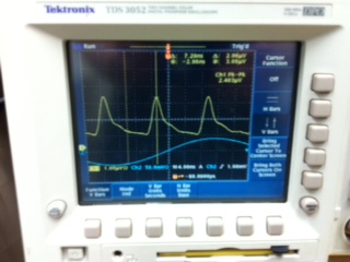
In the end of this part, rough numbers were taken based on slowly changing the current controller by hand. With the oscilloscope, photometer and a function generator hooked up the numbers could be double checked. The numbers weren’t guesses with small errors, they were relatively large ranges that ran very close to one another. Below is a table showing one of the sets of data that was taken of the 52S1/2 (F=1) and 52S1/2 (F=2) to the 52P3/2 hyperfine transitions for 85Rb and 87Rb
The transitions are in order of lowest current applied to the LASER to highest; corresponding to largest wavelength required for transition to smallest wavelength (all around 780.1nm,3.843*1014).
On the left is the transition (The frequency deviation from the center point state above.) The center and the right are the lower and upper values from the current controler respectively
| Δfrequency | lower (mA) | upper (mA) |
|---|---|---|
| -4.352 GHz | 43.38 | 43.72 |
| -1.771 GHz | 42.22 | 42.37 |
| 1.256 GHz | 44.00 | 44.27 |
| 2.483 GHz | 41.40 | 41.53 |
Using these values a GHz/mA ratio was found to be 2.353. The ratio was to be used to measure the line width. The pzt on the Fabry-Pérot wasn't working, so the function generator was to be hooked up to the back of the current controller passing over a known range. The peak on the oscilliscope could be measured with this known range and then with the GHz/mA ratio the line width would be found.
Fabry-Pérot
The LASER beam was directed into a Fabry-Pérot and the photodiode placed behind it. The idea: to see a few distinct peaks on the oscilliscope where the LASER beam resonates perfectly in the Fabry-Pérot as the current value was swept on a small scale. There was too much noise in the signal that couldn’t be interpreted, most likely because the LASER beam wasn’t perfectly aligned through the Fabry-Pérot.
It wasn't until after we had finished with the semester and our attempt at this project that Metcalf remembered to tell us that the line width of a LASER could be measured with a ruler
Click Here to see more pictures of the equiptmentReturning Weeks of August 2012
After getting back from a short break I was able to spend a couple weeks at the lab before the semester started. I was not able to witness ARP forces in the experiment, but I did become very familiar with the entire set up and the process needed to turn on the equiptment.
Little Personal Project
What is LASER Cooling
Many family member asked me what I was doing during the summer, but I had a hard time explaining to them what it was without being able to reference pictures. So I created a powerpoint presentation and setup a dropbox so that anyone can see the model I made about LASER Cooling.
Disclaimer: This powerpoint was not made by a professor or any other accredited member of the physics community. Its contents and statements should be taken with the knowledge that its author is an undergraduate student, and as such all information is an attempt to simplify complex physics by a student that doesn't fully understand them himself.
Monday & Friday, 16 & 13 July 2012
Monday a lot of work was done checking the many different parts of the experiment where there could be error, and running little tests on each one to check the setup and prepare to have everything up and running again. There was another meeting with Hal that was over an hour and we talked about very random topics like: properties of electric and magnetic fields of light, the ability to manipulate them, and their interaction with matter. These statements are obviously broad; specifically there were two things that were talked about: why the mathematics involving the schrodinger equation for spontaneous emission requires a lot of work to get to, and optical molasses.
On the 13th I actually got to couple light into a fiber. The setup was already there I just had to realign the mirrors and maximize the intensity out the other end. Which was substantially easier to do with the LASER beam that was being used. There are still tricks I need to learn, like how to properly move the lens inside the input coupler, but It is very nice to know I can do it.
Wednesday & Thursday, 11 & 12 July 2012
The amplifier that was shipped to France on my first day in the lab had finally returned on the 11th. There was a problem when it arrived, that it required a minimum of 10 dBm and all that was used in the past was about -0.3 dBm. A day that started off exciting with my first real day into the lab to learn about the equipment used, quickly changed when this problem was realized. John emailed the company and asked if it was a simply software problem that could be fixed.
On the 12th, as a last and final resort, I asked a student in the LTC (LASER Teaching Center) who had been working on different methods of efficiently coupling light into a fiber to help. We tried our best for about an hour and couldn’t do any better. John walked in asking if it was time to abandon the project, we agreed and he decided to tell me that the software problem was fixed and that we could actually start in the lab again. Since then I’ve been in the lab in the mornings trying to follow what is going on and remember everything I can.
Thursday, 5 July 2012 -> Tuesday, 10 July 2012
So from about July 3rd to July 10th I had spent the time trying to get this LASER beam, as bad as it was, into a fiber. Mirror’s were placed close to the end of the telescope and we tried walking it in first with a security camera to see the inferred, then a power meter. That was unsuccessful, so a spherical telescope was used first to magnify x4.4, then switched to shrink x4.4. Every graduate student and myself spend a considerable amount of time trying to get more of the light through the fiber. Most aspects of the setup were moved, poked, cleaned, and a couple times replacement parts were used. After doing everything the best that could be done, there was barely any reading on the power meter.
Tuesday, 3 July 2012
The beam coming out of the cylindrical telescope wasn’t as good as expected. Directly after the the second lense it was a very small circle that looked great, but a half a meter away the shaped started to deform. A faint ‘tail’ was on the circle on the same axis as the long axis of the original beam. I had hoped that the tail was only a small week glimmer and that the small nice circle behind the second cylindrical lens could be kept at that size and used for the experiment.
Passing a razor blade in front of a power meter showed that about 15 cm from the cylindrical telescope the most intense part of the beam was at the center, and the distribution resembled a gaussian (a good start). About 60 more centimeters down the table the beam diverged a significant amount. The same experiment concluded that about ⅔ of the light was concentrated from the left ‘edge’ to the middle of the beam, and the ‘tail’, representing the rest of the beam, had about ⅓ of the total intensity. After seeing this, I knew that the ‘tail’ couldn’t be ignored and I asked a graduate student for help. Apparently the beam was good enough to be used close to the cylindrical telescope Before I knew it three different graduate students were taking turns helping me out with the next steps to couple the light into a fiber. For reasons yet to be known, not much success was achieved; perhaps thursday will be better.
Thursday, 28 June 2012
Thursday Morning
The situation I have been trying to fix is that the LASER beam isn't
spherical; its parabolic with a rough 4 to 1 ratio
I had set up the cylindrical lenses (f=100 & f=25) to make a telescope and
individually measured how they
affected the beam shape. The screen was set a good distance away and I
looked for the point when the cylindrical lens was orthogonal to the long
axis of the beam(to produce a long thin line).
I plotted the size of the angle of the lense against the long axis of the beam. This way I could shift my horizontal reference frame to be that of the long axis and adjust the lenses accordingly. In attempting to do so I found an error of about 15 degrees; which is quite awful. I put the numbers into Maple, called a function to fit the data with a parabolic curve, and found the peak of the graph.
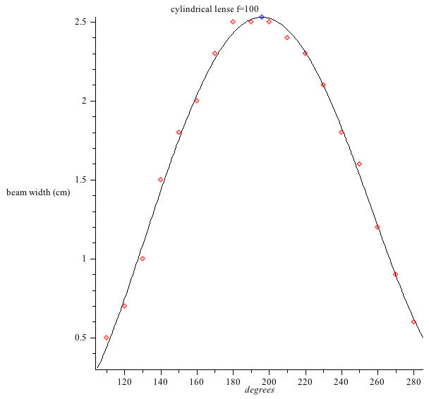
This was done for each lense sepparately.
Then I took the angle associated with the highest peek and set the cylindrical lenses. The angle of the lense that caused the beam to expand the most is the angle desired since the screen is >> f. The beam improved significantly, but still diverges- today I expect to fix that.
Sidenote: I'm still slowly trying to understand the syntax of Mathematica. My biggest hurtle in the beggining was the difference in the GUI from Maple to Mathematica. Simply trying to efficiently navigate around the help page is different challenge on its own.
Monday & Tuesday, 25 & 26 June 2012
Monday and Tuesday were different than normal days. I still talked to the grad students and Thomas for some of the time, and did a little bit of reading. Most of the days were comprised of me in the lab with the diode LASER I had started fiddling around with on Friday. It was a different feeling to have a goal and to spend the entire day running around the lab turning on/off various lights, hunting for the right piece of equipment that worked, and trying to jerry rig some kind of set up for a short test. Tuesday I spent around eight hours in and out of the lab, and at the end of the day It felt like the only thing that got me to leave was a need for dinner. I like having a project with no clear guidelines and no supervision. Its a really free feeling to just go in and do your best in whatever way you feel like.
I also learned a lesson that is probably a very important one. A mistake or momentary lapse in judgement could easily set you back an hour. So it is always better to step back and think carefully about the next step if there is any doubt.
Friday, 22 June 2012
Friday was a really good day overall. When I first arrived, I had a discussion with a friend who was doing theoretical research in a very strange topic that I won’t attempt to explain; all I can say is it had to do with the schrödinger equation and heavy elements. After the group meeting, Dragan went into the lab to attempt to align a beam. He was quite good at it for never having tried it before. As for me, I decided to turn on a different LASER and was having some fun attempting to make the elliptical beam circular with a cylindrical lens. I have never used a cylindrical lense before, but as long as the properties of it are intuitive then I think I can get a relatively good result. I don’t expect to spend an enormous amount of time on this, but I would really like to see how far I can get.
At the end of the day there was the first social of the summer. I liked being able to walk around and see the people I had seen in passing all week just relaxing and being themselves. It was a whole new context to see people in.
Wednesday, 20 June 2012
Yesterday Chris gave me a tour around the lab as he was setting up for his experiment. While he was working Brian and Thomas would explain some of the things that he was doing. It was really nice to finally be in the lab while one of these experiments was being set up to see what it took to get everything working. It was especially educational because he hadn't been in the lab in about two and half weeks. This time gap caused a lot of the set up to fall out of alignment, and I got to see more of what work is required from square one than I would've seen on a normal day. Something major that I really didn't expect was how many different pieces of equipment were required to get the desired LASER beam perfectly. Then after it was coupled into a fiber it was led into the next room where the interaction being studied actually happened. There isn't much to be said about what I learned as far as the set up, it mostly just aided me to connect any pictures or simplified drawings to what physically exists.
Today I learned how to walk a LASER beam. I would like a lot more experience with this in terms of what arrangements of the mirrors will work. As it was today Brian had me set up a He Ne LASER on a straight line with a lens and a mirror; perpendicular to the second mirror; then two very small holes perpendicular to the second mirror. The first time I was quite slow getting started, but by the third time I started to feel really comfortable with it.
I did learn a lot of simple yet not so obvious things like: any metal on you can reflect a LASER beam into your eye; if you have to bend down while the LASER is turned on, you should close your eyes as they pass the horizontal plane the LASER is propagating in; you should know exactly where the LASER is because even if it doesn't hit your eye it can still burn you; the static charge from a human can burn out a diode; directing the LASER beam back into the cavity can cause the amplifying material to never work properly again; liquid nitrogen is dangerous, but only in relatively large quantities; drops of liquid nitrogen evaporate from the thermal radiation being emitted from your skin; liquid nitrogen is quite cheep and really cool to work with.
Friday, 15 June 2012
These past few days have been incredibly interesting in terms of the
conversations that I have been involved in. For a long time I was learning
some interesting things about the equations and the language that is used
for these three particular experiments (ARP, STIRAP and Bichro).
However, recently I have been learning and hearing some things that truly
cause me to think. Two of which were questions that were directed to us
undergraduates in the group: one by Bruce, one by Hal.
Topics
- Forbidden Transitions: Metcalf wrote down an equation on Thursday that made sense as he put it together, but when he explained the significance of the r term I was shocked. He explained that it was in some way representative of the radius of the electron, and that some transitions actually weren't possible. I didn't expect this to be true for any atom. I had assumed that as long as the resonant frequency was attainable with no detuning in a perfect environment, that any transition desired could be made.
- Jayne Cummings model:The first question Bruce Shore had challenged us with directly was a specific situation of the Jayne Cummings model. There is a single atom and a single photon in a confined controlled space (box). Imagine the photon is off resonance with the atom, perhaps in between two energy states. The atom can only absorb specific quantities of energy to move to an excited state, but it is known that the probability of finding an atom in this situation excited is not zero. So how does this make sense? As he is a theorist he explained it with an equation; the Hamiltonian has three parts for this situation: the atom, the radiation and the interaction. This third part is the misterious hidden part where the energy hides. I have written the answer this way because I don't fully understand the Hamiltonian that I am referring to; which is again pointed out in the 'questions'.
- Infinite excited states for EVERY atom: The work function varies for each element, but no matter the element, there are inifinite excited states attainable. The energy required to ecite the atom for each state increases, but the difference in energy required between each state decreases. This makes it possible to have infinitesimal energy states in a finite area. I had always had this idea that for a perticular atom there were excited states with a decreasing 'distance' between each state, but after a set amount of states the electron would have enough energy to leave the atom. In this case there would be a finite limit of energy levels for each atom dependant on the work function. In reality the work function may vary but no matter the value there are infinite states squeezed in the set bounds.
- Protons, Neutrons & Excited States. No atom absorbs energy unless the light hitting the atom is on resonance with one of the discrete energy levels of the atom. I had always imagined the nucleus as a kind of classically behaving ball, with this weird quantum mechanical electron flying around. As a ball the nucleus could absorb all values of energy, even though large amounts could break it. At specific low energies the electron would react, and the nucleus would have some change in say linear or angular momentum. In reality, the nuetrons and protons act the same way as the electron, there is simply much more energy required to excite them.
- Controlled Direction of Stimulated Emission: When one of the graduate students was talking they mentioned something about the direction of stimulated emission being controlled to some extent. I didn't really catch how this was accomplished or any actual information about it, but it was definitely something that caught my attention.
Questions
- What is stark shift?
- What is that third part of the Hamiltonian?
- Why is it so hard to make powerful LASERs? Light bulbs were invented a long time ago - MASER was invented a good amount of time after that - Then finally LASER. I know the technology in the light bulb and the LASER today is substantially different, but still I don't see what was so difficult. I simply am curious about what makes LASER such a difficult thing to create. In practice I have heard that it is common to use frequency doubling to get a LASER with a desired frequency. If in medicine there are x-ray machines and controlled gamma radiation, then why in physics is it so hard to get LASER at such a high energy? What is it about LASER that makes it so difficult?
Tuesday, 12 June 2012
Yesturday Bruce Shore had a long discussion with the
group about defining the differences between LASER cooling and selection.
Zolte Kis gave a presentation at about four, most of which I couldn't
understand. Fortunately it did lead to a small discussion with Brian about
vibrating nonlinear material by use of piezoelectric material with a well
controlled AC voltage. The voltage was induced upon the piezoelectric
material (which expanded and contracted), causing a piece of quarts to
vibrate at about one hundred mega hurts. The quarts was chosen because it is a
nonlinear piece of material. When the LASER light would pass through the
quarts some of the light would receive a small vertical perturbation
(perpendicular to original direction of propagation).
The properties of the nonlinear material that cause it to affect light in
such a way have to do with what happens when the light strikes the
molecules in this particular material. The light goes in and undergoes all
sorts of effects that cause different kinds of interference and slowing
that in the end effect the frequency of the light.
In this situation the quark can be described as a phonon; another term
that of which my understanding was fuzzy before yesterday.
Today
A great topic of discussion was one that Metcalf is well known by his
students to have interest in: the difficulty in defining a photon. In
general Metcalf avoids the word in its entirety in a attempt to treat
light purely as a wave, but yesterday him and Bruce Shore
discussed/argued/debated the possible ways to define such a word in great
detail. It was very interesting to finally hear the reasons
why there isn't always a well described/agreed upon
definition for a 'quanta' of light.
At about two, Bruce gave a lecture covering basically every topic that I have been attempting to understand in the past two weeks. He approached it really slowly - defining all the variables and explaining their origin. He went on to overview some of the different ways one can shine/pulse light onto a two/three level atom. Tomorrow there is to be a lecture that will be perticularly helpful to me. As much reading as I have done, understanding how to use the bloch sphere to help describe some of these things is an idea I have yet to grasp.
Friday, 7 June 2012
Yesturday I met up with Thomas and Adam to learn the basics of assembling a circuit with a breadboard. Not much was accomplished since the oscilliscope we were trying to use wasn't familiar to any of us. Today I am trying to translate some worksheets I have written in Maple into notebooks in Mathematica.
Tuesday, 5 June 2012 - Thoughts and Questions
In roughly a week I will actually start working in the lab on one of the projects that Metcalf supervises. For now I would like to write down some general understanding of the physics involved.
Light on its own has momentum, this momentum can be transferred to cause a physical object to move in a particular direction. In a simply theoretical example a man floating towards the sun can pull out a MASSIVE reflective 'sail' that will catch the sun's rays and push the man away from the sun.
For a more relevant look we will think about helium on an atomic scale. A photon is shined on an atom that has momentum moving to the right. The atom's momentum decreases by the absorption of the beam of light. An electron quickly decays accompanied by an emission of fluorescent light, but this time in a random uncontrolled direction. Extending this reaction to numerous atoms close together, the net direction the atoms are moved due to stimulated/spontaneous emission is roughly zero. In a sense the only thing that has changed is the horizontal speed of the atoms. As the speed decreases the temperature decreases (Temp proportional to square of velocity), and eventually the atoms can be reduced to a temperature below 1 Kelvin.
QUESTIONS: I understand that there would be infinitely many velocity distributions, but as long as they have the same kenetic Energy then why is it in correct to characterize them as the same "temperature"?
How much significance does the specific velocity distribution of the atoms have (at least to the topic of LASER cooling)?
If the average velocity of the atoms is in the desired direction why should the specific velocities matter?
Would the width/size of the sweep be dependant on an average distribution of velocities for the atoms, deviating only slightly away from the average velocity?
If the purpose is to slow down the atoms then wouldn't the frequency of the LASER have to account for the change of velocity from near 300 m/s to near 0 m/s; since atoms moving at 300 m/s would have a different doppler shift as opposed to those moving at 0 m/s?
I understand that the atoms are initially cooled with liquid nitrogen (inital velocity wouldn't be ~300m/s). My point is just that the purpose is to decrease the velocity of the air molecules by a substantial amount, and this substantial change in velocity must be accounted for.
Claim: I'm pretty confident that this statement is correct, but it will need to be verified near future. It appears that the frequency sweeping of the light is due to the need for numerous different frequency for each air molecule as they do not all have equal velocities or even accelerations. There is a doppler shift that is a result of the atom absorbing the momentum of the light and therefore changing velocity. The width of the sweep would then be dependent on a calculation of possible velocities/accelerations and the different frequencies of light needed to resonate with these specific atoms.
Monday, 4 June 2012
Dr. John Noe showed me around the LTC today and had me start this webpage. We briefly discussed random topics about waves and optics relating to PHY 300. I brought up the peculiar circumstance that occured during the speckle lab when the LASER beam was directed onto an iPhone screen (turned off): much to my surprise little circles appeared in a grid-like pattern spaced a significant distance apart! Dr. Noe immediately brought up that this kind of chance observation is what prompts research.
Home Page