Research Journal
SUMMER 2013
August 16th, 2013
It's hard to believe that it's already the end of the summer. I don't know what I'm going to do with myself when I'm not spending most of my day in the lab. This summer has been an fantastic experience that I hope to repeat in future summers. I can't thank the Dr. Noé, Marty, Melia, Hal, and Dave enough for encouraging, helping, and pushing me thorough out the course of the summer. I had a great time and I learned a lot as well.
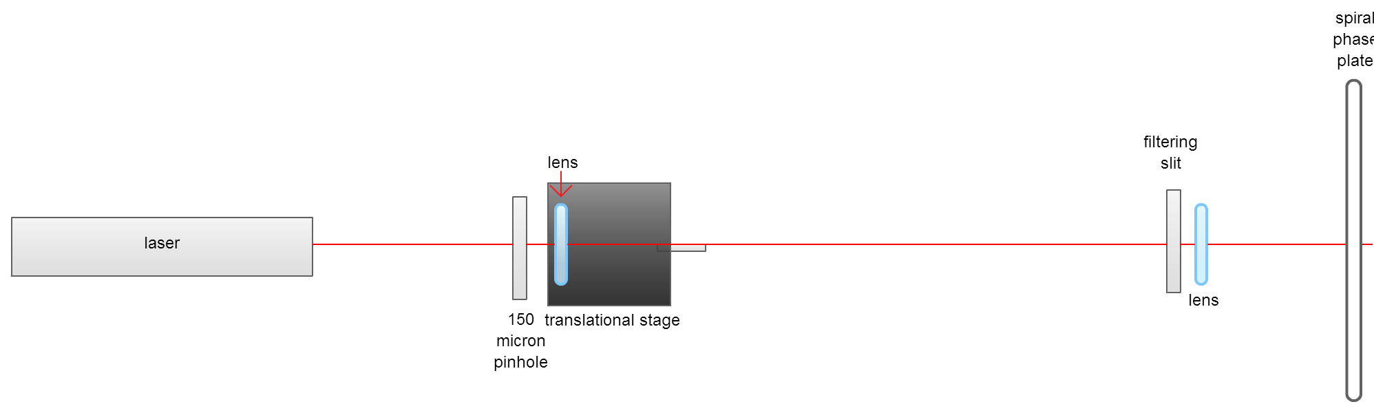
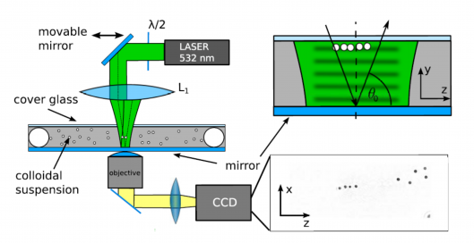
When I come back for the fall semester [a little over a week from now], I would like to 1) model the Fresnel diffraction from the pinhole, the diffraction from the filtering slit ilumminated by the Fresnel diffraction pattern from the laser and single mode fiber, and the light as it passes through the spiral phase plate; 2) profile the diffraction pattern from the filtering slit and the beam after it passes through the spiral phase plate in the far field; and 3) study the diffraction pattern that results when the Fresnel diffraction pattern from the single mode fiber passes through a circular aperture. See ya soon!
August 15th, 2013
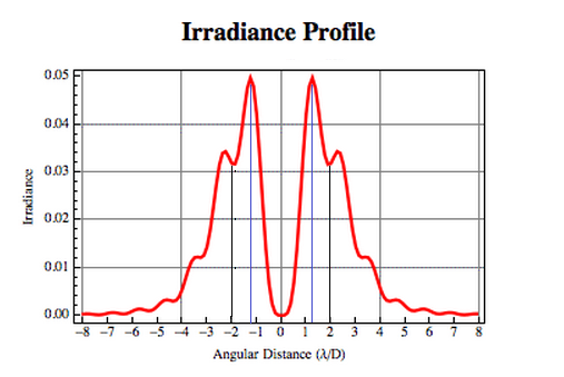
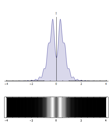
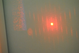
I realized yesterday that the experimental diameter of the Airy diffraction pattern central disk I had measured when testing for super resolution was incorrect. I thought the diameter I had measured was approximately 0.21 mm, but it was actually around 1.02 mm. This would make the experimental diameter of the Airy central disk almost four times as large as the theoretical diamter. This seemed improbable, so I looked over our math again and I think I found the source of error. I'll explain our calculations before I go into why I think they were wrong.
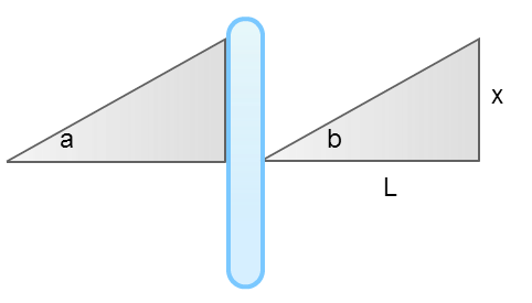
Our goal was to find the theoretical diameter of the central disk of an Airy diffraction pattern. In Airy diffraction patterns, sin(θ)=1.22λ⁄D, where D is the diameter of the circular aperture producing the diffraction pattern. We then used the small angle approximation [sin(θ)=θ] to find the angle at which the light struck the lens. We then used the angle we found from the first calculations, the fact that sin(b)=x⁄L, and the small angle approximation to find x, the diameter of the central disk in the Airy pattern.
I think our calculations made two incorrect assumptions: 1) that an Airy pattern would have formed by the time the light hit the lens [the lens was not in the far-field from the aperture]; and 2)that the lens would not change the angle of the angle at which the light was travelling.
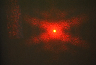
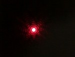
I was having trouble figuring out how to factor the lens into my equations, so I decided to not use a lens in my set-up and calculate what the diameter of the central disk would be at the far side of the hallway [26.7 meters away]. I found that the central disk should be roughly 15.9 mm in diameter using sin(θ)=1.22λ⁄D and the sin(θ)=x⁄L. When I measured the diameter of the central disk on the far side of the hallway though, it only measured on average 4.2 mm in diameter. That's almost four times smaller! I did read in a paper that annular pupil-plane filters in combination with radially polarized light could produce resolutions of λ⁄4, so the number I got could be possible. I would like to profile the beam before I celebrate getting such improved resolution though. I'll probably do that as soon as I return for the fall semester.
After I measured the diameter of the central disk of the Airy pattern, I set about mounting the single mode optical fiber to a translational stage and shone it through a 100 micron pinhole. It was very easy to reproduce the patterns that Will observed. I was also able to easily create "optical vortices" using the spiral phase plate.
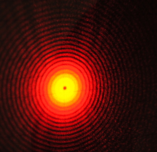
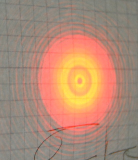
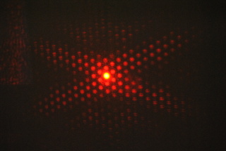
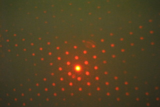
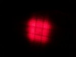
I was curious whether illuminating an aperture with the diffraction pattern, that looked much like the Fresnel diffraction from a circular aperture when N=2, would produce similar super resolution. To test out whether illuminating an aperture with this diffraction pattern causes super resolution, I used the diffraction pattern to illuminate the 2.9 mm aperture the shop made me and observed the diffraction pattern in the far-field. I was surprised to find that even 12 m [well within the far-field] from the circular aperture, the diffraction pattern was not an Airy diffraction pattern. Instead, the diffraction pattern looked almost like it was almost imaging the aperture. The diffraction pattern was composed of a dark central dot surounded by very thin concentric dark and bright rings with the brightest and thickest ring being the outermost one. The diffraction pattern I observed is very curious and I would like to study it farther.
Dr. Noé talked to Kiko Galvez from Colgate today about many things, including my project. Dr. Galvez forwarded a paper to Dr. Noé that showed how to produced improved optical vortices using a spiral phase plate through the use of axicon lenses. The intensity distribution of the light this group sent through the spiral phase plate looks similar to the intensity distribution of the beam I am sending through the plate. I am very excited by the paper. Kiko also mentioned the Berry paper on optical vortices that I mention in an earlier post, so I will have to look over that again. on The next step seems to be to profile the optical vortice I produce using the filtered diffraction pattern in the far-field and model it in MatLab. There isn't enough time left in the summer to model what is happening to the light as it passes through the spiral phase plate, but I will get to work on that as soon as the school year starts.
August 14th, 2013
It's crazy to think that the summer is almost over, just when things are starting to get interesting too. The beam that I created yesterday is almost definitely not a Laguerre-Gaussian beam. Dr. Noé talked to Lowell Wood yesterday, the author of the paper which inspired my entire project. Dr. Wood mentioned that the light that hits the filtering slit would be out of phase; this means that when the light hits the spiral phase plate, the light is not in phase, so a perfect helical beam will not be formed.
The next step that I would like to take is to model the Fresnel diffraction pattern resulting from the original pinhole and model how the beam of light changes as it passes through the spiral phase plate. We contacted Will Weiss, a former LTC student, about how he modeled Fresnel diffraction from a circular aperture, but have not heard back from him yet. While I don't think the beam I created is a Laguerre-Gaussian beam, I still think it is interesting though and would like to study it further.
We had our weekly lunch today followed by a short lecture by Hal. Casey, Seth Berl, James Dragan, and I all presented what we've worked on this summer. Casey presented on his work with Fabry Perot interferometers. Seth and James gave a presentation together on their work with John Elgin on his adiabatic rapid passage experiment; Seth also presented some of the simulations he created for Chris' experiment. I gave a presentation, Attempting to Create Optical Vortices, which highlighted some of my recent progress. I realized that I had incorrectly calculated my super resolution numbers before and so I am going to recalculate and remeasure them tomorrow.
Hal gave a talk today on the Bloch equations [inspired by Seth and James's interest]. Hal started by showing us the Schroedinger equation and then added in the light interaction. From there, he showed us Rabi's equations and showed us how Feyman, Vernon, and Hellworth were able to solve the same problem using a different method by only dealing with real numbers. Lastly, Dr. Metcalf made mentioned the Bloch equations, which can describe any two level system that can be explained using physics. I was able to follow it alright, but I don't understand it well enough to teach it to someone else. I guess that's alright though because I still have three more years left at Stony Brook.
After the talk Dr. Noé increased the output from the coupled fiber and we were able to view the Fresnel diffraction patterns that Will Weiss' project dealt with. I plan on mounting the fiber tomorrow so I can study the diffraction patterns resulting from a pinhole illuminated by a single mode optical fiber.
August 13th, 2013
A lot happened today! Before when I created optical vortices using the N=2 beam, I was getting concentric rings surrounding the optical vortice and when I moved further away from the spiral phase plate, rings started to form in the center of the optical votice. I believed that these inner and outer rings were due to the fact that the light was still diffracting from the first aperture. The diffraction pattern formed by the first pinhole only has a Fresnel number of 2 for an infinitely small time; the second before and after the filtering aperture, the Fresnel number is not equal to two. I figured out that I could remedy this problem by inserting a lens a focal length after the filtering aperture, so that the beam as it passes through the aperture is essentially imaged at infinity. I observed the beam at varying distances from the filtering aperture and found that the pattern did not change as I moved farther away from the filtering slit.
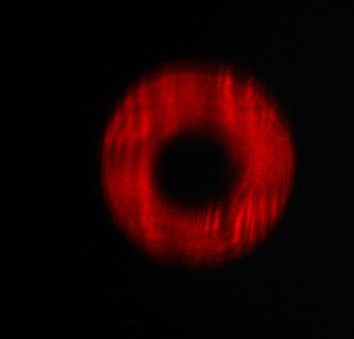
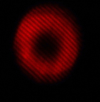
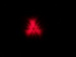
When I sent this beam through the spiral phase plate, the inner and outer rings disappeared and an optical vortice with a sharp edged boundary was created. Dr. Noé is skeptical about this beam being a true Laguerre Gaussian beam. He said that I could verify this by profiling the beam. I can also test whether the beam is an optical vortice using an interferometer.
Stefan, Casey, and I also worked on coupling a single mode fiber, some light is transmitted, but the output could still be higher.
August 12th, 2013
I spent this morning creating optical vortices using the spiral phase plate. I was suprised by the low-quality of the Laguerre-Gaussian beams the plate created. I mistakenly thought that sending the Gaussian beam through the spiral phase plate would create a donut beam with a few radial streaks; the beams that were produced by the plate were actually donut beams with concentric rings dark and bright rings. I found that when I moved farther away from the spiral phase plate the middle of the beam developed concentric rings within it. After seeing this, I think that using the beam when N=2 does produce improved Laguerre-Gaussian beams, although they are not perfect. I'm going to experiment more with creating optical vortices by both methods.
I'm starting to realize that I know very little about optical vortices and how they are supposed to look. I started reading the optical vortice resources on Azure's page. I was excited to read in one of Berry's papers that the edge of the step in spiral phase plates causes scattering; I am glad we are not the only ones observing this.
Stefan, Melia, and I spent some time fiddling with my set up trying to create improved optical vortices. We attached the spiral phase plate to a translational stage, so that it's easier to adjust the position of the plate. I noticed that the reflections off the back and front of the spiral phase plate were forming interference patterns.
Melia and I also coupled a fiber.
August 8th, 2013
I spent the majority of this morning pouring over Will Weiss' page. His project is pretty much the opposite of mine. In my setup, I have a fixed source and I get the different Fresnel diffraction patterns by moving the imaging plane and in his setup, he has a fixed imaging plane and forms the different Fresnel diffraction patterns by moving the source. His setup sounds better for producing improved optical vortices than the set up I am currently using because the Fresnel diffraction pattern is actually the Fraunhofer diffraction pattern of the aperture [because the aperture is non uniformly illuminated], which means the shape of the diffraction pattern won't change as you move farther from the aperture. All I would have to do after the beam left the aperture is collimate it and then I could send it through the spiral phase plate.
August 7th, 2013
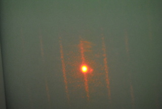
I found evidence of super resolution today! The 2.6 mm aperture uniformly illuminated and lens I am using would produce an Airy pattern with a central disk of diameter 0.24 mm. I profiled the Airy produced using the aperture illuminated by the diffraction pattern from a circular aperture when N=2 and the diameter of the central peak measured 0.21 mm. I am very excited by this result because it shows super resolution and is a reasonable sized difference between the diameters of the two. I was especially excited because it was perfect timing for me to present at today's pizza lunch.
Today was the Simon's students' last pizza lunch; it's odd to think that the summer is almost over. All of the students' gave presentations today and Melia presented a slideshow of pictures from this summer. Everyone's presentations were very good. My presentation was entitled Creating Inverse Apodization Using Circular Apertures and dealt with my work with the Fresnel diffraction patterns from circular apertures. Hal brought up my past presentations on Babinet's principle and mentioned that using the principle, if you had an opaque object the same size as the aperture, when N=2 the diffraction pattern would be the inverse of the diffraction pattern I am filtering [the middle would be high intensity]. He suggested that I extend my project to study this as well.
I got a chance to talk to both Dr. Noé and Marty today about modeling the Fresnel diffraction from a circular aperture. Dr. Noé said that the diffraction pattern could be calculated numerically. I am still a little confused on how this works though.
In trying to find the equations for intensity distribution in Fresnel diffraction from circular apertures, I stumbled across some good information pertaining to my project.
Babinet's Principle: Babinet's principle states that complementary sets of obstacles [one set has openings where the other is opaque] produce the same diffraction pattern. Imagine complementary screens produce diffraction field Y1 and Y2 at a point P on the imaging plane, then Y1+Y2=0 and Y1= -Y2. This explanation helped me understand the reasoning behind why complementary sets of objects produce the same diffraction pattern because the amplitudes of the two sets are negative versions of each other and intensity is equal to the amplitude squared so they have the same intensity.
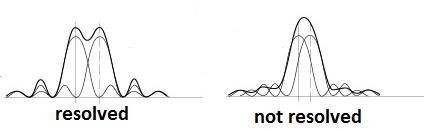
Diffraction Limited Resolving Power: If the component separation between two objects is small enough, the composite image appears to be a single object. Objects are said to be resolved at a separation where the composite image is first judged to be the product of two objects. This occurs near the separation where the center disk of one Airy pattern is over the first dark ring in another Airy pattern. For two circles, the necessary angular point source separation for the image to be resolved is αR=1.22λ⁄w.
August 6th, 2013
Yaaay, my filtering apertures are finished!!!! I asked the shop to make a 2.6 mm and 3.9 mm in diameter circular aperture for me yesterday. The 2.6 mm circular aperture transmits from the center to the first maxima of the beam, while the 3.9 mm circular aperture transmits from the center to the first minima. I am going to use the 2.6 mm aperture to see if using this beam produces super resolution and the 3.9 mm aperture to create the optical vortices.
The filtering apertures were finished after lunch, so I spent the majority of my morning working on my report and abstract. I had a chance to talk to Dr. Noé about my abstract today and he suggested I start the abstract talking about Lowell Wood's paper.
The Simons students toured the LTC today so I didn't have much time to work with the filtering apertures. I did get my set up aligned though, so I will be ready to profile the diffraction pattern from the 2.6 mm aperture tomorrow. For the Simons tour of the LTC, I showed the kids a laser light show and talked a little about my research. The research seemed a little over most of their heads [many of the students hadn't had physics yet], but they seemed to enjoy the laser light show.
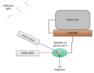
The light show was comprised of a HeNe and HeCd laser, a speaker, a glove, a CD fragment, an amplifier, and a boombox. A glove was pulled taut over the face of the speaker and a CD fragment was glued to the glove and the lasers were both placed so that they shined onto the CD fragment. When music was played, it would vibrate the front of the speaker, which in turn vibrated the CD fragment and caused the reflected laser light to form different figures [It was extra cool because the tracks of the CD act as a diffraction grating so there were multiple figures from each laser]. We observed that the figures were bigger when the notes were lower; this is because the lower notes have a lower frequency.
August 5th, 2013
I finished a first draft of my abstract over the weekend and continued to work on my report. Hopefully, there will be time over the next week for me to meet with Dr. Noé to discuss my abstract. I spent the majority of today continuing to work on my report. The machine shop is also going to make me two filtering slits. One that is 2.6 mm, so from the center to the peak of the first maxima will be transmitted, and another that is 3.9 mm, from the center to the second minima will be transmitted.
August 2nd, 2013
Yesterday, I profiled an Airy beam as a control to make sure I knew how to profile a beam correctly. It worked out pretty well, which I am pretty excited about.
Today, I profiled the beam where the Fresnel number is equal to two, so that I could calculate the size of the filtering slit we need.I found that we need a 2.6 mm filtering slit; I'll have to ask the shop to make one for me.
July 31st, 2013
Jenny Magnes and three of the students working in her lab, Tewa Kpulun, Brian Deer, and Ramy Abbady, made the journey all the way from Poughkeepsie to Stony Brook today to visit the LTC. When they first arrived, I talked to them for a while about my interests, the project ideas I've had, and Fresnel diffraction. Professor Magnes was quite interested by the Fresnel diffraction patterns from the circular aperture because their work up until this point has only dealt with Fraunhofer diffraction patterns and she was curious about the possibility of also using Fresnel diffraction patterns. I've been working hard to understand the concepts behind my project and was happy that I could answer most of their questions.
During our weekly pizza lunch, Dr. Magnes, her students, Kathy, and I all gave presentationa. It was interesting hearing about Dr. Magnes' work. There was also a biologist from Stony Brook, whose name escapes me, that attended the presentations who was interested in biophysics, who I should talk to sometime. My presentation was titled Optical Diffraction and Biology and talked about the project ideas I have had and their relation to biology.
I also got a chance to work with Stefan to create some optical vortices using the spiral phase plate. The vortices were still a little dirty though and our technique needs to be refined. Marty suggested that I profile the diffraction pattern from the 1 mm aperture in the far field to make sure my technique is correct.
July 30th, 2013
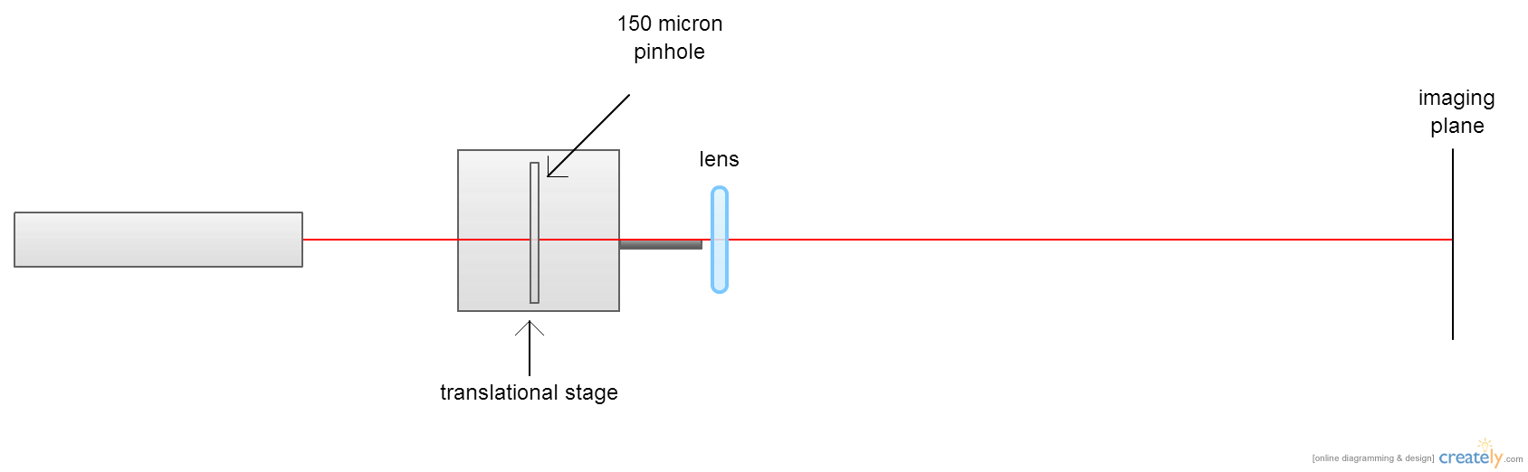
Today, I profiled the diffraction pattern resulting from a 150 μm pinhole illuminated by the laser beam where N=2. I made sure that I was in the zone where N=2 rather than one of the other even Fresnel number zones, by positioning the lens so that the Fraunhofer diffraction pattern was projected onto the plane, N<1 and then moving the lens closer until the intensity in the middle was equal to zero. I measured the intensity at the middle using a photodetector.
I am a little confused on how to compare this data with the diffraction patterns if the aperture had been uniformly illuminated because I don't know how to calculate the magnification after the converging lens because M=di/do because do=infinty meaning the magnification is 0, but the image is clearly smaller. I'll have to talk to Marty about this.
I also worked on the presentation I am going to present tomorrow.
July 29th, 2013
I got a chance to look at the photos I took on Friday using the CCD camera and attempted to analyze them using ImageJ. The photos were not high enough quality to be used for quantitative purposes though.
I talked to Marty some about my project and he suggested that I use a regular lens rather than the microscope objective because the opening of the objective is very small and it's possible that not the entire diffraction pattern was being transmitted. [I had noticed more back scattering with the objective in place.] After talking to Marty, I switched my setup back to using a regular lens, f=35mm. I had profiled the diffraction pattern from a 1 mm aperture in the morning, but I am going to redo it. The diffraction pattern resulting from the 1 mm pinhole should be able to tell us whether using the beam where the Fresnel number is even produces super-resolution. Based on the measurements I took this morning, it looks likely; the central peak was skinnier and the outer lobes had greater intensity.
July 26th, 2013
Marty showed me a paper a little while ago in which the authors had been able to attain optical super-resolution using annular apertures. We wanted to see if using the beam where the Fresnel number was even [zero intensity at the center, same as the annular apertures] would produce super-resolution as well. I tested this by adding a second pinhole, 1 mm in diameter, to my setup in between the first pinhole and the imaging plane. I then positioned the objective so that the Fresnel number was even when in the plane of the second aperture and positioned the aperture so that the hole matched up with the center of the diffraction pattern. Lastly, I imaged the diffraction pattern resulting from the second aperture in the far-field.
I took photos of the Airy diffraction pattern using both the Electrim CCD camera and the Nikon camera. I did not have a chance to look at the photos taken with the CCD camera because they are on a floppy disk; I will try to look at them on Monday [Seth Berl said that Hal's lab has a machine which allows you to read the floppy disk on your own computer using a USB cable]. I did look at the photos taken using the Nikon camera though. I tried getting the intensity distribution of the photos using ImageJ, but the photos are not high enough quality to be used for this purpose. I also made the setup so that I can profile the diffraction pattern using a voltmeter on Monday and created a program in Mathematica, which models the intensity distribution from a circular aperture.
July 25th, 2013
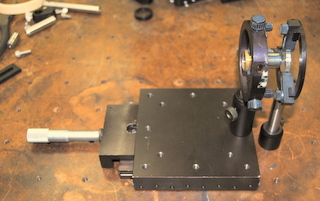
I replaced the lens in my set up with a 10x microscope objective because the objective magnifies the pattern more. The magnification of the objective is about 140x. Its focal length is about 1.6 cm. Marty suggested that I try imaging the aperture, rather than the plane where N=2 because this would magnify the pattern along all three dimensions (x, y, and z). We tried this and it was successful. By moving the imaging plane (a piece of white paper) up and down the path of the beam, we were able to observe the pattern change as the Fresnel number changed. In order for the objective to image the aperture, it has to be very close to the aperture (~4mm); it was very difficult to get the aperture close enough. After trying a number of convoluted- and unsuccessful- methods to get the objective close enough, I was finally able to devise a simple way to get the objective close enough using a lens holder.
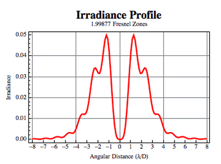
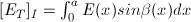
After looking at the equation for
the on-axis intensity from a circular
aperture,  , I understand why the intensity is zero
when the Fresnel number
is even. When the Fresnel number is even, the sine will be of a multiple
of 2π, which will always be equal to zero. Here is an example of what
the diffraction pattern looks like when the Fresnel number is even:
, I understand why the intensity is zero
when the Fresnel number
is even. When the Fresnel number is even, the sine will be of a multiple
of 2π, which will always be equal to zero. Here is an example of what
the diffraction pattern looks like when the Fresnel number is even:
July 24th, 2013
Today was very productive. I started off by calculating the
width of the
filtering slit needed to only transmit the desired portion of the
signal for various aperture diameters. I did this by entering the
wavelength, aperture diameter, and distance where the Fresnel number is
equal to two for the observation distance into an application,
created by James Wyant, and then used the irradiance profile the
application created to calculate the angular distance of the filtering
slit
needed. I then multiplied this by the distance from the
aperture to where
the Fresnel number was equal to two to find the diameter of the
filtering aperture
needed. I also used  to find how far from the
aperture I should place the lens.
to find how far from the
aperture I should place the lens.
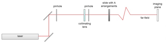
I had created a set up yesterday, which consisted of a laser, two pinholes, a collimating lens, and an iris, but I wasn't able to observe a diffraction pattern with a zero intensity center though. When Marty came in, he told me that my set up was more complicated than it needed to be and that all I needed was a laser, a lens, and a pinhole to observe the diffraction pattern with zero intensity. We ended up mounting the lens on a translational slide so that we could make fine adjustments in its position. At the end of today, my set-up looks like this:
At our pizza lunch today, Giovanni Milione, former Stony Brook undergraduate and LTC researcher and currently a graduate student at City College, gave a talk entitled Classical Entanglement with a Vector Light Beam. The talk focused on-what he referred to as-classical entanglement between the spin angular momentum and orbital angular momentum of vector vortex beams. The talk was very interesting and helped me entanglement a little better. After Giovanni's talk, all of the students in the LTC gave a quick one minute (they ended up being closer to three) summary on what they are working on currently and the context for their research. We also had a chance to tour Dominik Schneble's ultracold atomic physics lab. They produce and perform tests on Bose-Einstein condensates. I was impressed to learn that their lab is able to produce the coldest thing in New York State; they can cool atoms to about 7 to 9 nano-Kelvin.
July 23rd, 2013
Casey and I found a HeNe laser and its matching power supply today. The HeNe has a power of 15mW, which should be good for our purposes. I constructed a holder for the laser and aligned a 150 μm pinhole, then a collimating lens, and lastly an iris to collimate the beam. I added the iris so that only the central disk of the Airy pattern is transmitted. I collimated the beam so that the next aperture will be uniformly illuminated. I added in a 1 mm circular aperture and observed the diffraction pattern where the Fresnel number is equal to two. I did not observe a dark center like I expected. I think it may be either because the diffraction pattern was too small to see the dark center. I'll have to ask Marty and Stefan when they come in tomorrow.
I also found an equation
to calculate the Fresnel number, N, at a
distance z from a circular aperture,  . To
maximize apodization, we should filter the diffraction pattern where N=2.
The reasons for this are two-fold; the
intensity at the center of the diffraction pattern is equal to zero when N
is even and the area of the center zero intensity area is largest in
comparison to the total area of the diffraction pattern. I was surprised
to find that with a 160 μm circular aperture,
N=2 approximately 5.06 mm from the aperture. I found
that using a 1 mm aperture, N=2 approximately 19.8
cm from the aperture or using a 2 mm aperture, N=2 about 79.0 cm
from the aperture. Using a 1 or 2mm circular
aperture would probably be ideal because the relative uncertainty will be
lower. Also a longer distance will give non-parallel rays a longer time
to travel away from the central beam. I still have to calculate the
correct size for the filtering aperture. I found a paper,
which should help me do this.
. To
maximize apodization, we should filter the diffraction pattern where N=2.
The reasons for this are two-fold; the
intensity at the center of the diffraction pattern is equal to zero when N
is even and the area of the center zero intensity area is largest in
comparison to the total area of the diffraction pattern. I was surprised
to find that with a 160 μm circular aperture,
N=2 approximately 5.06 mm from the aperture. I found
that using a 1 mm aperture, N=2 approximately 19.8
cm from the aperture or using a 2 mm aperture, N=2 about 79.0 cm
from the aperture. Using a 1 or 2mm circular
aperture would probably be ideal because the relative uncertainty will be
lower. Also a longer distance will give non-parallel rays a longer time
to travel away from the central beam. I still have to calculate the
correct size for the filtering aperture. I found a paper,
which should help me do this.
Dr. Noé, Melia, Kathy, and I had lunch at the Simon's Center today with Urszula, a former Stony brook PhD student who was in the LTC for a short period learning about optical twezers. Urszula was very knowledgable and it was great talking to her. She seemed to be a master of both biology and physics.
July 22nd, 2013
I looked over the single-slit diffraction pattern application again today
and figured out where the equations they used came from. The creators of the application used Feynman's
method of integrating over paths. Using this method, the slit was
first divided into n
equally spaced points and the path was assumed to consist of two
rectilinear parts one from the light source to one of the n points and
from the point to the screen. The vector, which describes the
light, rotates as the light travels reaching the same phase angle after
it has traveled
a wavelength, λ because of this property you only needs to know a
fractional part of the length of the path divided by λ to find the
angle of the path at the end. This method is used for the n
paths and the amplitude for each path is the sum of the
wave vectors that form that
path. The creators of the application used
the equation 
 , where
n is the number of dots
and j is the number of the point.
, where
n is the number of dots
and j is the number of the point.
I made a slight change to the application, changing the wavelength from 630 nm to 632.8 nm because our HeNe lasers operate at 632.8 nm. It did not significantly change the patterns. Below is the application I have been referring to:
I talked to Marty quite a bit about aperture functions. He thought that it would be easier to optimize apodization with circular apertures because the shop is better equipped to make small holes than it is to make small slits. We looked at the diffraction pattern intensity distribution using an application. Where the Fresnel number is equal to two seems like a good place to observe the diffraction pattern because the intensity of the beam at the center should be zero. Marty and I were having trouble thinking of applications. We tried to think of some application where the image would be fuzzy and then by using the aperture functions the image would become clear. So far, we have come up with observing the diffraction pattern in the far-field to see if it is super-resolved. Dr. Noé said that shining this kind of beam through the spiral phase plate would be another good extension. I am interested in aperture functions, but would still really love to recreate an object from its diffraction pattern and would love to find some way to incorporate this project into the aperture function one.
I was also very excited to learn that Jenny Magnes from Vassar will be visiting the LTC with a couple of her students next week. Hopefully by that time I will have some data to show and talk about. Dr. Noé said that Jenny will be giving a presentation on the phase problem and a new solution she has come up with. Dr. Noé also told me that I will be giving a presentation when Jenny visits. I am excited to talk to her about her research.
July 19th, 2013
I spent this morning looking over the books Marty and Dave lent to me
yesterday. Marty lent me Lasers,
by Anthony Siegman. The book has a section on diffraction
patterns from a
single-slit and the
equation for the intensity
of
the diffraction pattern from a single-slit in
the Fresnel zone,  . I plan on
using this equation to calculate the intensity distribution of the
diffraction pattern at different distances from
the slit, so that I can find a portion of the diffraction pattern, which
would maximize apodization. I'd like to create a program which models the
intensity
distribution of the diffraction pattern from a single slit as a
function of distance from the slit. Using an application
I found, which models the intensity distribution of the diffraction
pattern
from a single slit illuminated by a HeNe laser, I looked at the intensity
distribution of the diffraction pattern at 1 m from the slit with
different slit widths. It seems that the ideal intensity distribution,
greatest apodization, occurs with a 2.06mm slit. I'd like verify this
mathematically for myself though.
. I plan on
using this equation to calculate the intensity distribution of the
diffraction pattern at different distances from
the slit, so that I can find a portion of the diffraction pattern, which
would maximize apodization. I'd like to create a program which models the
intensity
distribution of the diffraction pattern from a single slit as a
function of distance from the slit. Using an application
I found, which models the intensity distribution of the diffraction
pattern
from a single slit illuminated by a HeNe laser, I looked at the intensity
distribution of the diffraction pattern at 1 m from the slit with
different slit widths. It seems that the ideal intensity distribution,
greatest apodization, occurs with a 2.06mm slit. I'd like verify this
mathematically for myself though.
I also looked at the book Optical Holography, which Dave Battin lent me. The book discusses using Fourier holography for pattern recognition. It was a little over my head, but I was able to find some of the papers the book referenced, which helped me understand the concepts better.
I also downloaded Mathematica. I read a couple tutorials and played around with the coding for a single-slit workbook to familiarize myself some with Mathematica.
July 18th, 2013
On a whim, I deicided to look at Jenny Magnes' webpage today. I was surprised to find that many of the things she has been writing about on her blog mirror what I've been writing about in my journal, such as the phase problem, oversampling, and phase retrival.
I talked to Marty more about the Lowell Wood paper he had sent me and Marty also showed me another paper on optical super-resolution, resolution better than conventional diffraction-limited resolution. They were able to achieve higher than average resolution using pupil-plane annular aperture filters [the middle of the beam is blocked out]. The annular aperture filters create a similar effect to the aperture functions created in the Lowell paper, but the aperture function doesn't create such an abrupt edge between the light and dark though. Marty mentioned that he thought you could create a better apodization effect from a single slit and after looking at the intensity distribution from a single slit using this application I would have to agree. Marty and I talked about the possibilty of creating an better apodization effect and then shining the beam at different object's to see how the diffraction pattern differs from if the object had been illuminated with a uniform beam. He gave me a book to learn more on the topic. Dave Battin also gave me a book to look at that talks about Fourier holography.
I've written that you need both the phase and amplitude of a diffraction pattern to reconstruct the image that made it, but up until this point, I haven't been clear why. The answer is Babinet's principle, which states that the diffraction patterns of complementary diffractors are identical in the far-field. In more understandable terms, this means that an aperture and an opaque object of the same shape and size will have the same diffraction pattern. For example, both a circular aperture and opaque circle will form an Airy ring diffraction patterns.
Holography is a technique for preserving the phase information needed to retransform an image from its diffraction pattern without a lens. It accomplishes this by recording patterns of interference fringes caused by the interactions between two coherent beams. In the Fourier holography method, light diffracts around a reference aperture, a small scatterer, and interacts with the light diffracting from the sample. The phase of the reference waves varies simply in the imaging plane and when the diffracted waves interfere with them, the diffraction pattern forms a record of the phase of the diffraction patter relative to the reference beam.
This is shown in the proof below [Keep in mind that we measured intensity which the amplitude of the Fourier transform squared]:
the Fourier transform created by the sample and the scatterer will have an off-axis geometry, making it easy to seperate and retrieve the object image and the conjugate using a single Fourier transform of the scattering intensity.
July 17th, 2013
Marty sent me a paper yesterday about diffraction projects that we would be able to do in the LTC. The paper was very interesting and dealt with experimentally creating aperture functions.
Apodization is the reduction in the amplitude of the secondary maxima in diffracted light. It is used in signal processing, digital audio, and in astronomy and can be achieved using aperture functions with higher transmission at the center than the edges. A lot of mathematical work has been done on aperture functions, but very little has been done experimentally. This paper seeks to rectify this gap.
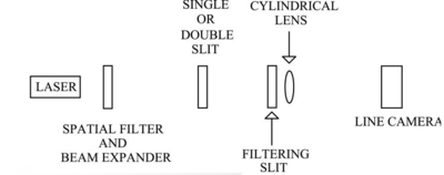
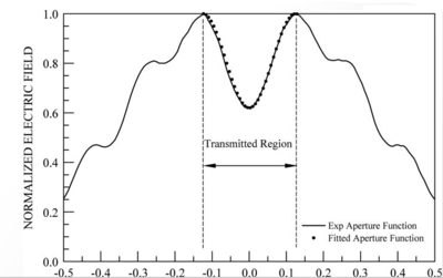
Light is sent a through single or double-slit aperture, both of whose diffraction patterns are well understood, and then a filtering slit, so that only the desired portion of the diffraction pattern is transmitted. Using this method a variety of aperture functions can be created, including the full-sine, cosine, and half-sine aperture function. The paper found excellent agreement between the calculated and experimental values. This technique could eventually be used in optical beam shaping and would make it so that the number of possible aperture functions is only limited by one's imagination.
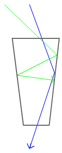
We also had our weekly pizza lunch today. I learned a lot. We started off the lunch with a presentation by Sam Goldwasser from the extremely informative Laser Sam's FAQ. He talked about different types of lasers, longitudinal modes, and Fabry-Pérot interferometers. After that each of the students working in the lab gave about a ten minute presentation on what we've been studying. My presentation was titled Fun with Diffraction and dealt with the diffraction patterns I observed from the arrangement of A apertures, reconstructing an object using its far-field diffraction without a lens, and forming aperture functions. Hal mentioned that apodization literally means cutting off the feet. He drew a funnel and explained that apodization selects against light coming in at a shallow angle, but transmits light coming in at a steep angle. This sounds similar to how apodization can be achieved in one-dimension using an aperture with higher transmission at the center than near the edges. Hal said that this process was used in our eyes to ensure that we don't see light internally reflected in our eyes. Hal also said he would forward me a paper on the topic.
I had a chance to talk to Dave Battin briefly about Fourier holography. He said that he did know some about Fourier holography and said that when holograms were first invented the US military used Fourier holograms for pattern recognition, for example to find Russian planes. He said that he had always wanted to make one. I'll have to look more into the topic. It is very interesting and I'm sure my dad would love it if I did a history based project.
July 16th, 2013
Light detectors, such as CCD cameras, only measure the intensity of light that hits them. This produces an incomplete picture of the light wave though because light has both amplitude [related to the intensity] and phase. The phase information is lost in measurement. This loss is referred to as the phase problem. The phase problem represents a fundamental limitation in our abilities due to the nature of measurement in quantum mechanics and is an issue in both diffraction and image formation. So the question is how to save the phase information that our long detection times generally destroy?
I. The Single Slit Problem
For a single-slit,
 as the
Using integral calculus, this can be written
 , where
x is the position
of the source point in the slit. E(x) is obviously zero though everywhere
except
0 ≤ x ≤ a, therefore
, where
x is the position
of the source point in the slit. E(x) is obviously zero though everywhere
except
0 ≤ x ≤ a, therefore

 or
or
II. Fourier Transforms
As I've stated in earlier journal entries, a Fourier transform is a method of describing functions in terms of sinusoids. It is the most common mathematical tool in advanced physics. The purpose of Fourier transforms is to change the emphasis of information. For example, you may know how particles are spatially distributed, but want to emphasize the (related) distribution in momentum. Fourier transform can be used to relate these two pieces of information.
Frauhofer diffraction patterns, like the one formed by a single-slit, are
Fourier transforms of the original object. Looking
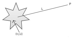
at the equation for the phasor from a point source (x,y,z), which is
 . In the general case, the amplitude of the
electric field at P is the sum of many phasors,
. In the general case, the amplitude of the
electric field at P is the sum of many phasors,  ,
which is mathematically a Fourier transform, where
ET(xo,yo,zo) is the
transform of E(x,y,z). Both functions contain the same information
organized in a different manner.
,
which is mathematically a Fourier transform, where
ET(xo,yo,zo) is the
transform of E(x,y,z). Both functions contain the same information
organized in a different manner.
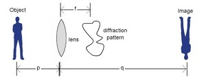
Lens are able to retrieve an image that has the same shape as the original object. The lens brings the diffraction pattern in from infinity and retransforms the diffraction pattern into an image. The Fourier transform [diffraction pattern] reorganizes the information and the lens organizes it back.
July 15th, 2013
I looked over the paper about lenless imaging Dr. Noé, Melia, and I found on Wednesday some more over the weekend and it seems that the topic would make for a good research project. The authors of the paper not only describe the project they did in-depth [which they see as suitable for graduate or undergraduate students with some adjustments] and invite interested parties to contact them with any questions, but they also make some suggestions for related projects. The two ideas they suggest are skipping the reconstruction method and instead using a Fourier holography method to image the sample and collecting images of the sample from many different views, so that a 3D animation can be made. While the second idea sounds interesting, it may be to complicated to accomplish in a summer. The first suggestion on the other hand sounds interesting, accomplishable, and original [to the best of my knowledge].
The authors of the paper stumbled across the idea of using Fourier holography to image the sample by accident. When the authors looked at the Fourier transform of the diffraction pattern's measured intensities of an insect's wing, they noticed that there were three images of the wing: a central correlation of the specimen and two weaker images of the insect wing.
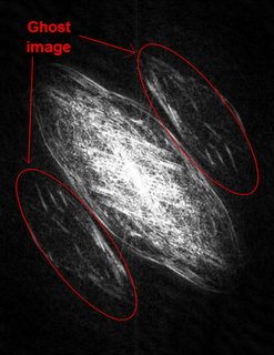
The weaker, ghost images, are the result of interference between the scattered light from the wing and a small additional scatterer unintentionally in the field of view. The small scatterer allows for Fourier holography method to be used. Holograms are patterns of interference fringes, which encode the interactions between two coherent beams. In the Fourier holography method, when the fairly coherent wavefront of the scattered light from the small scatterer interferes with the arbitrary wavefront scattered from the sample, electric field information, including amplitude and phase, can be found. This method solves the phase-problem through the use of a reference "aperture" next to the sample, the interactions between the waves diffracting from each source is recorded and the phase can be recovered from it. This information can be used to reconstruct the sample.
After talking to Melia and doing some research online, it seems that ImageJ would work well for a project like this because it is able to compute the Fourier transform and subtract the background from an image. I also found a couple of resources today, which I think should help me understand the optics behind this project.
When both the phase and intensity of the diffraction pattern from an object are known, it is possible to reconstruct an object's image. The intensity of a diffraction pattern can be obtained by imaging the diffraction pattern, with for example a CCD camera. [The intensity is also proportional to the square of the amplitude of the Fourier transform of an object image.] The phase cannot be directly obtained using diffraction measurement though. This is referred to as the phase problem. Oversampling is a solution to the phase problem.
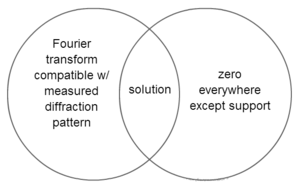
Oversampling occurs when the sample to be reconstructed is surrounded by a sufficiently-large uniform and featureless area. A small sample area, support, compared to the field of view can provide enough constraint to ensure uniqueness of the solution. By assuming that the area not within the support has zero density, when the zero density region is larger than the support, more than half of the total information about the object is known in real space, which makes it possible to make up for the missing phase information. By sampling the diffraction pattern sufficiently finely, the phase problem is over-constrained, meaning no solution exists which satisfies all the constraints, and the reconstruction is unique.
Oversampling works because while there is more than one image whose Fourier transform is consistent with the measured diffraction pattern and there is more than one image that has zero values everywhere except within the support, if you oversample a sufficient amount, there will only be one image which meets both of these conditions. This principle is demonstrated in the Venn diagram below.
The paper suggested that a unique reconstruction can be obtained if the diffraction pattern is oversampled by a factor of two in both orthogonal directions or the linear dimensions of the reconstructed specimen has to be less than half the number of pixels along both the x and y axes.
Picking a sample to reconstruct is one of the most important and most difficult parts of this project because very few objects are weak scatterers in the visible light spectrum. Strong scatterers have complex-valued reconstructed exit-waves, making phase retrieval harder. They also make it difficult to collect 3-dimensional data sets and so that all optical elements must be in pristine condition because even small specks of dust can dramatically reduce the quality of the data. Reconstruction can be forced to be real-valued though, if the specimen is flat. A photographic slide for example is thin and uniform enough to only affect the incident wave through absorption, which leads to an effectively real-valued exit wave modulation. Transparency slides with printed patterns should also work.
July 12th, 2013
This morning Samantha talked about her experiences with Python and Dr. Noé showed us some good resources for project ideas. Samantha used Python in her past research to create graphs and animations. Dr. Noé suggested that we use the American Journal of Physics webpage and Optics Info Base to find ideas and papers for our project. He showed us how to search the databases and find interesting articles.
I read more about reconstructing an object's image from its diffraction pattern. The paper I read was originally written for the American Association of Physics Teachers and was intended to teach students about diffraction microscopy and coherent diffractive imaging.
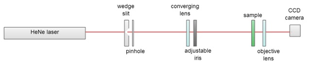
The set up described in the paper had two main parts: a collimator and detector. The collimator included a HeNe laser, with λ=632.8nm and a nominal power of 5mW, whose intensity was controlled using a sliding wedge-slit; a pinhole; a collimating lens; and an iris. The purpose of the collimator is to produce a parallel beam. The detector was made up of the sample, a collector lens, and a CCD camera. The purpose of the detector is to capture the image of the diffraction pattern.
In the described collimator, the laser first passes through a sliding wedge-slit, which controls the intensity of the beam. This causes the beam to scatter, so a very small pinhole [in the paper a 50 μm pinhole was used] is placed immediately after the wedge slit. The pinhole must be small enough that the phase difference between the light that passes through the extremes of the aperture is much less than the wavelength of the light. This allows the rays act as if they are parallel and making the illumination of the pinhole effectively uniform.
The beam is then collimated using a converging lens placed one focal length in front of the pinhole. [In the paper, a 200mm lens was used, resulting in a 3mm radius beam.] An airy ring diffraction pattern forms after the light travels through the pinhole, but only the central disk of the pattern is needed to illuminate the sample, so an iris is used to eliminate the higher order lobes of the Airy pattern. After the laser travels through the collimator, a nearly parallel beam should emerge.
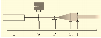
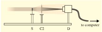
Next, the laser travels through the detector half of the set-up. While in theory it should not matter how far your sample is from the collimator, the authors found that the greater the distance between the two, the higher the quality of the diffraction pattern. This occurs because the light is not perfectly parallel when it leaves the collimator and so the extra distance between the collimator and the sample allows the nonparallel components of the beam [which arise from scattering off dust] time to gradually propagate away from the central beam. After the beam passes through the sample, it passes through an objective lens, which focuses the diffraction pattern onto the CCD camera. It is important that focused diffraction pattern be smooth on the scale of one detector pixel when it hits the CCD camera. This lens forms the Fourier transform of the sample's exit wave in the len's back focal plane.
July 11th, 2013
I learned a lot today. For most of the morning, I looked for diffraction-related research projects that didn't involve bacteria. Then in the afternoon, Stefan showed me how to align your set-up and I observed the diffraction patterns of different arrangements of A's [hexagonal lattice, rectangular lattice, random, and arranged in a single row] in the far-field.
Estimating Onion Cell Size Using its Diffraction Pattern
Melia was able to find a paper yesterday on estimating the size of epidermal onion cells using their diffraction pattern. The epidermis in onions is composed of like-shaped and -sized cells. Because the cell walls are opaque, while the center is transparent and the cells are relatively uniform, the onion cells act as one-dimensional transmission diffraction gratings.
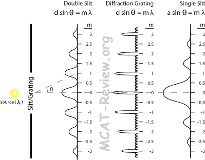
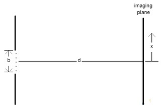
In the paper, the fact that epidermal onion cells produce diffraction patterns similar to the diffraction patterns of one-dimensional diffraction grating was exploited to estimate the transverse width, the shorter of the two dimensions, of the onion cells. The distance between the maxima in diffraction grating, and epidermal onion cells, follows the equation, dsinθm = mλ. To find the transverse width, a laser is shone through the onion tissue and the distance between the central peak and the second order maxima is measured for different distances between the onion cells and the imaging plane, L. The results were then checked by measuring the transverse width using microscopy; the values were close, but were not consistent. The author believed the error came from different cell's transverse width being measured by the laser than the microscope. It seems like a set-up could be designed that could shine a laser through the cells and measure the width of the cells by microscope, so that the slide didn't have to be moved and the same cell was for sure being measured.
I also read a lot about using diffraction patterns to reconstruct images, but I am still a little unclear on how it works and will have to read more on the topic.
I also found a program, called Diffraction, which will model the diffraction patterns of different apertures for you. It's functions are limited by the fact that you can only choose a point, circle, or rectangular aperture. You are able to set the radius of the apertures, number of apertures, distance between apertures, wavelength, and intensity though.
Yesterday, Dr. Noé mentioned to me that we have a slide with different arrangements of A's on it. He thought that looking at the diffraction patterns that resulted from the different arangements of A's would help me understand how bacteria arrangements form diffraction patterns. I found the slide in the diffraction demonstration drawer.
Before I could observe the diffraction patterns though, I had to align the optical elements. I haven't dealt with the laser much, so Stefan taught me how to align the different optical elements. It was really helpful. Here are some of the things I learned:
Aligning Optical Elements
Always make sure your beam is traveling in a straight line down the table; make sure it doesn't travel slightly to the left or right because at far distances little mistakes are amplified
When aligning a pinhole, first align the pinhole by adjusting the height and horizontal placement of the pinhole close to the element before it. Once it is aligned, measure the distance from the edge of the table to the pinhole. Then move the pinhole back to the desired distance from the prior optical element, making sure the pinhole is the same distance from the edge of the table, and then adjust the prior optical element until the beam travels through the pinhole
Steps for aligning a collimating lens:
Move the collimating lens back one focal length from the last optical element
Line up the lens so that the laser hits at approximately the center of the lens
There will be a reflection from the front and the back of teh lens, which will appear as a small and large dot. When these two dots are aligned with the incoming laser beam, the lens will be aligned. To get the dots at the same height, you adjust the height of the lens; to get the dots at the same place horizontally, you move the mirror to the left and right.
Once we got the set-up aligned, we shined the laser beam through the different arrangements of A's and observed the diffraction patterns. At first, I was suprised by the patterns we were getting, but as we went on it became more evident how they were formed. When we moved the paper close to the slide (about a foot away), we observed an x pattern for every arrangement of A's. When we moved further from the slide, different diffraction patterns arose that were related to the way the A's were arranged. For example, the row of A's produced bands of intensity similar to if there had been multiple slits. Dr. Noé' thought this was because at that the shorter distance we were in the far-field for the A, which caused the x diffraction pattern, but were not yet in the far-field for the overall pattern.
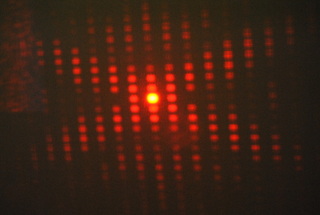
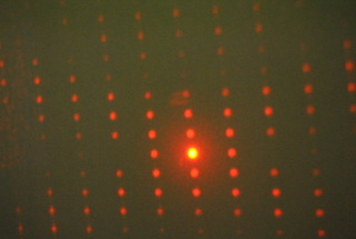
After searching around for a bit, I discovered that these slides were designed by Ronald Bergesten for the American Association of Physics Teachers apparatus contest to demonstrate Laue diffraction. It sounds like both Laue diffraction and Bragg's law would be good things to learn more about.
July 10th, 2013
Today was Samantha's first day in the lab. She gave a really nice presentation on her research finding misclassified blue stars in the Sloan Digital Sky Survey, SDSS. After her presentation was finished, we had our weekly group meeting.
Dr. Noé told to us about his meeting with Kiko Galvez on Sunday. They talked about a number of topics; I was most interested by their conversation on spatial light modulators, SLMs. At this point, Dr. Noé is thinking of buying a Hamamatsu and a Cambridge Correlator SLM. The Hamamatsu is high-quality and will be reserved for special research projects, while the Cambridge Correlator is lower quality and will be good for exploration. Dr. Noé said that MATLAB is often used to control the SLMs, so I am going to try and learn as much as I can about MATLAB before the SLMs arrive. I found a tutorial produced by the company that created MATLAB that looks pretty useful.
I talked to Dr. Noé about my project; he encouraged me to stray away from the bacteria aspect of my proposed project and maybe focus on something like modelling scatter patterns using molded plastic or something else. Talking to him more, we came up with some more ideas, such as printing something out on a transparency sheet and observing its diffraction pattern and recreating objects using their diffraction patterns, also known as lensless imaging. Dr. Noé encouraged me to look further into diffraction by a 'whole lot of little things', identifying things with diffraction, and diffraction around soft edges. He suggested Euiwon Bae, John Sokolov, and Jenny Magnus might be good people to contact about my project.
July 9th, 2013
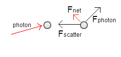
Reading an issue of OPN, I stumbled across an article on optical tractor beams. An optical tractor beams is a beam of light that can pull an object toward the source of illumination. They are different from laser tweezers, which trap a particle, but do not move objects 'up' the laser beam.
At first glance optical tractor beams seem impossible; when the photons in a laser beam hit a particle, momentum is conserved and the particle travels forward away from the light source. If you think of the laser beam as a stream and the particle as a rock, it becomes obvious why it is counterintuitive that a particle should move up the laser beam. Just as rocks don't move upstream, it seems neither should particles move towards the source of a laser beam. Researchers, such as David Grier and Pavel Zemánek, have been able to experimentally realize optical tractor beams though and an even greater number of research groups have showed that there exists a theoretical basis for optical tractor beams.
In an ordinary beam, each photon moves in the direction of the beam, so when a photon encounters an object it bounces directly back from the object and imparts the greatest possible forward force on the particle. For optical tractor beams though, a beam is used where the photons travel at an angle relative to the light source, so when the photons encounter an object, it imparts a reduced forward force. [One experiment used pseudo-Bessel beams, which were created by overlapping light waves at an angle relative to the desired direction of flow.] When the photons interact with the object, they polarize the material electrically and magnetically. The now polarized object then radiates and redirects the light. By adjusting the material properties of the object and the polarization and synchronization of the individual light waves in the beam, the object can radiate more light away from the light source than towards it. This pushes the particle towards the light source by overcoming the reduced push forward from the photons. So far the optical tractor beam has been used to move particles less than 500nm in size up to 30 μm. Optical tractor beams could have applications in cell sorting. Sadly, we don't have a laser with enough power to create one in the LTC.
I also read about solenoid beams, which were created by David Grier using a Hamamatsu spatial light modulator. I would be very interested in studying them once we get our SLM.
July 8th, 2013
I've been thinking a lot lately about how to turn my project concept, imaging bacterial colony scatter patterns, into a research project.
What's the next step? What concepts do I have to understand before I start this project? What do I need for the set up? What controls do I need to establish and what are the variables? How many trials should I run?
These are just some of the many questions I've been mulling over in the back of my head for weeks. I've looked into the cameras that other studies used and we have comparable, although our CCD camera has a slightly larger pixel size and lower resolution. We also have lasers that operate at the same wavelength, 632 nm, as past studies used. The main thing holding me back from getting my project started today is culturing and growing the bacteria. In order to go from a bacterial sample to colonies, I would need to culture the bacteria, make and inoculate the plates, and incubate the sample.
Below are some of the kinks in my project that I will have to work out before my project becomes a reality and my tentative solutions:
SBU would have a fit if we grew bacteria in the LTC: I thought I had read a paper about imaging the scatter patterns of yeast colonies. Trying to relocate the paper for this entry though, I realized the paper I had discussed imaging the scatter patterns of single yeast cells, not colonies. Yeast colonies should still be capable of creating unique distinctive scatter patterns, but I would have no pictures to compare the images of the scatter pattern I captured to. I will have to talk to Dr. Noé about how to address this issue.
How to culture the bacteria: E. Bae et. al. reported culturing their bacteria in brain-heart infusion broth, BHI broth. They grew the culture for 15-18 hours at 37 o C, about 98.6 o F or the internal temperature of humans.
What dilution to use: When growing a culture, it is impossible to know the exact cell concentration. Instead of trying to do the possible, conventional practice is to use serial dilution, the stepwise dilution of a solution, to innoculate plates with successively less concentrated solutions. The ideal concentration to be able to image distinct colonies, while having the largest sample size is about 30-50 colonies per plate, E. Bae et. al.
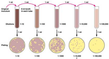
How to plate the bacteria: E. Bae et. al. reported growing their bacteria on agar plates composed of 40 mg trypticase soy agar and 1 L Millipore water (just purified water). They boiled the mixture for 1 minute and then poured the plates, about 25 ml in a 88 mm round plate. After the plates dried, they reported inoculating the plates with 25 µl of bacterial culture. They inoculated the plate using the spread method.
How to grow the bacteria: E. Hirleman et. al. incubated the plates for 18-36 hours or until the diameter of the colony reached 1.2-1.5 mm at 37 o C.
How to get the materials I need: All of the materials I would need are fairly common place in a biology lab, minus possibly the specific brand of trypticase [different brands can affect colony growth]. We are not a biology lab though. It would take about two to three days to make the plates, cultures, and grow the colonies. I found out one of my friends is working in an oncology lab in the HSC, maybe his lab would have the resources I would need.
On a side note, I also found a paper that used Fresnel patterns to identify bacteria type, which could be another possible project, and Kevin also emailed me the photos of the diffraction patterns from Friday, so here they are:
July 5th, 2013
I've heard the name Fourier tossed around quite a lot in the pass year: in relation to Angela's project, mentioned by Abby Flowers, and most recently in reference to scatter patterns. So what is Fourier optics? Fourier optics is the study of classical optics using Fourier transforms, a method of describing functions in terms of sinusoids, which is reversible.
Fourier optics is used in optical information processing [spatial filtering, optical correlation, computer generated holograms], interferometry, optical tweezers, atoms, quantum computing, and in determining the phase of light intensity in a spatial frequency plane. It can also be used to describe Fraunhofer diffraction patterns, which are the Fourier transform of the diffracting object, like the ones Melia and I made [July 3rd entry]. Fourier optics also play an important role in the formation of scatter patterns in that scatter patterns are the Fourier transforms of the diffracting colonies. Fourier transforms describe an object in terms of the individual spatial frequencies that make it up. One website I found compared Fourier transforms to finding the recipe for a smoothie:
"What does the Fourier Transform do? Given a smoothie, it finds the
recipe.
How? Run the smoothie through filters to extract each
ingredient.
Why? Recipes are easier to analyze, compare, and modify than the
smoothie
itself.
How do we get the smoothie back? Blend the ingredients."
In not smoothie terms, the Fourier transform is breaks a function into its symmetrical, sinusoidal components. The 'goal' of Fourier transforms are to find the sources of an observed outcome. The smoothie-analogy might seem silly, but the article presents Fourier transforms in a very relatable way and I would recommend it to anyone trying to grasp what Fourier transforms are.
Melia and I created diffraction patterns for the square and triangle aperture again, but this time Kevin took photos of them on his nice camera, so hopefully I will be able to put those up soon. I also added betterexplained.com to my links page. Betterexplained.com is a website that tries to explain math in the least 'mathematical way' possible, pulling in lots of examples and diagrams, the website makes it really easy to understand the concepts behind the equations and terms.
July 3rd, 2013
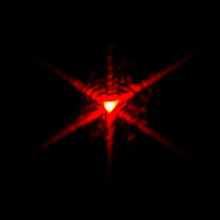
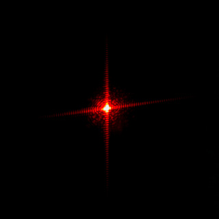
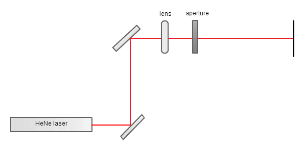
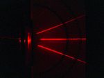
Today was awesome! To start off the day, Melia and I shined a laser through different apertures and observed the diffraction patterns. We tried it with a circular, triangular, and square aperture. I haven't had a chance to work with lasers yet and I found it rewarding to plan out the path of the laser and then align the mirrors, lens, and apertures, so that the laser beam traveled straight through.
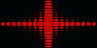
The circular and triangular aperture diffraction patterns we made matched the patterns I have seen online. The square one did not look match the diffraction patterns I had seen online as well and looked more like a cluster of squares in the middle with some squares extending vertically and horizontally than a single bright square with dimmer squares extending horizontally and vertically. The circular aperture produced an Airy ring pattern; the triangular aperture created a distorted curved edge triangle pattern; and the square aperture created a central square cluster pattern with vertical and horizontal squares extending outwards. We dimmed all the lights in the LTC and were able to observe the diffraction pattern about 13.7 meters from the light source. [I apologize for the quality of my photos. I only had my cell phone camera on me at the time. Kevin said that he will bring his nice camera on Friday, so hopefully we will be able to capture better photos of the diffraction patterns then.]
After lunch, Marty visited. I talked to him some about my project: an earlier more simplified set-up I had found and the properties of agar. Melia and I then talked to him about the diffraction patterns we had made in the morning. After talking to him, we realized that we had set up the beam expander incorrectly. Marty showed us how to how to properly set it up. The problem with our original beam expander was the light rays weren't parallel to one another; this was fixed in our second attempt.
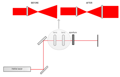
After we fixed the set up, we reobserved the diffraction patterns. The circle and triangle looked pretty similar to the original patterns we had created. The diffraction pattern from the square aperture however looked more like the patterns I had seen online. [We were able to create a cleaner diffraction pattern than the one pictured below by adjusting the lenses in the beam expander, however I do not have a picture of the cleaned up pattern.]
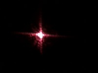
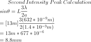
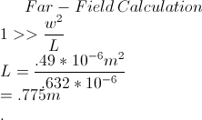
Marty then worked with me and Melia to calculate where the second intensity peak should occur and how far away from the aperture is considered the far-field when using the square aperture. We calculated that the second intensity peak should occur about 8.8mm away from the center of the central intensity peak. We measured the distance to actually be about 9.5 mm, fairly close to our predicted value. We also calculated that over 0.775m from the aperture is considered the far-field.
July 2nd, 2013
Inspired by the directory at the top of Melia's An Introduction to Spatial Light Modulators, I decided to reformat my Beginner's Guide to Linux. The top directory should make it easier to maneuver the page and give a head's up as to what content is covered by the page. [As an added bonus, if students wan't to learn how to create a directory themselves, they can just look at the page's source code.] After that the formatting bug bit me, so I reformatted my links page and my research journal. [I'm not sure yet if I like the new format; I might change it back.]
I also found a paper which specifies the best type of agar to use as well as the optimal drying time of agar plates to capture unique scatter patterns for E. coli. I was surprised by the results of the paper (mainly how short the drying time was- 10 to 20 minutes). I'm glad I came across it because I hadn't thought about how drying time would affect the scatter patterns.
I keep coming across the term Fraunhofer diffraction in my readings on bacterial scatter patterns. Dr. Noé has also mentioned the term to me once and brought up that sending a laser beam through different shaped apertures (circular, triangular, etc) and observing the diffraction patterns in the far-field should help me better understand the optics at work in forming scatter patterns and is a good supplement to my project.
Starting with the basics, when a beam of light is partly obstructed by an object, some of the light will bend around the object; this phenomenon is called diffraction. Fraunhofer diffraction occurs when both the light source and viewing plane are effectively infinitely far away from the obstruction. To be exact, it occurs when the distance between the object and the plane in which the pattern is observed is large enough that the phase difference between the light from the extremes of the aperture is much less than a wavelength, so that the individual contributions can be treated as if they are parallel (parallel ray approximation) or when w2/Lλ<<1. Fraunhofer diffraction takes place in either the far field or the focal plane of a positive lens. Ironically enough, Fraunhofer diffraction was named after Joseph von Fraunhofer, although he was not directly involved in the development of the theory.
In Fraunhofer diffraction, the wavefronts are planar. In the case of an aperture, the incident light being a plane wave makes it so that the phase of the light at every point in the aperture is identical. With lenses, all the rays have the same phase at the point of focus, which is equivalent to viewing the plane wave at infinity. The diffracted light after passing through a lens and aperture is a set of plane waves of varying orientation; this is because each plane wave was brought to focus at a different point in the focal plane with the point of focus being proportional to the x- and y- direction cosines, so that the positional variation in intensity is a map to the variation in intensity as a function of direction. These properties make adding up the contributions of the individual wavelets simpler. The diffraction pattern's shape and intensity are constant and independent of distance to the aperture or lens.
Rectangular aperture diffraction pattern: diffraction pattern in each direction is similar to that of a single-slit (rectangular peak with a series of horizontal and vertical fringes); the dimensions and spacing of the bands are related to the dimensions of the slit
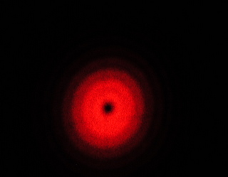
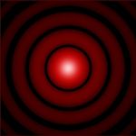
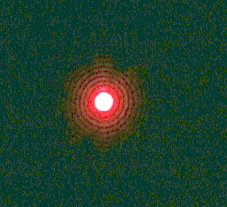
Circular aperture diffraction pattern: Airy ring diffraction pattern (bright central circular disk surrounded by concentric dark and light rings)
Grating diffraction pattern: first off grating is any arrangement which imposes on incident waves a periodic variation of amplitude and/or phase; spectrum
July 1st, 2013
The first day of July, hooray! Today, I am going to focus on the optical phenomenon at play in creating scatter patterns. One study found the scattering patterns of three Listeria species to be composed of Airy ring patterns, secondary bright rings in the middle of the diffraction patterns, random speckle effects, and radial spokes. All of these features can be explained using optics.
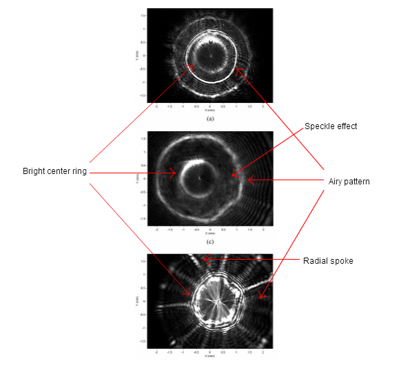
Airy ring patterns are made of a central bright circular region with a series of concentric dark and bright rings around it. Airy beams were named after George Biddel Airy; while he was not the first to observe the beams; he was the first to formulate a complete theoretical explanation of the beams. Airy beams are typically formed by uniformly illuminating a circular aperture; they can also be formed however by obstructing the middle of a beam with a circular object. This explains why Airy ring patterns were found in the scatter patterns formed by the Listeria species because the diameter of the Gaussian beam exceeds that of the colony, so that the colony acts as a circular obstruction. The portion of the beam that passes through the colony is attenuated (the intensity of the beam lessens), while the portion that does not pass through the colony is transmitted. This causes a phase- and amplitude- aperture effect producing an Airy ring pattern.
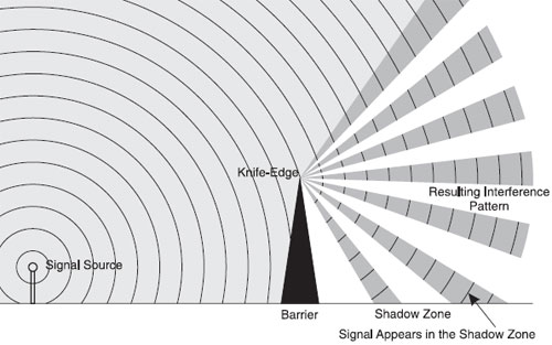
When radiation hits a well-defined object, a portion of the incident radiation is redirected as a result of diffraction. This phenomenon is referred to as the knife-edge effect, or edge effect. The behavior of the redirected light can be explained using the Huygens-Fresnel principle, which says a well-defined object that obstructs an electromagnetic wave will act as a secondary source and create a new wavefront. This phenomenon is responsible for the bright ring in the center of the Listeria scatter patterns. In Listeria colonies, the "knife-edge" is created by the difference between the transmission coefficients at the center and edges of the colony. At the center of the colony, transmission is influenced by the thickness [read a greater number of bacteria to absorb and/or scatter light] and the fact that the bacteria nearest to the agar surface are the oldest and have excreted the greatest amount of extracellular matter meaning there is a higher mass density. At the edges, transmission is greater because there are fewer and younger bacteria.
Speckle patterns are intensity patterns produced by the mutual interference waves. They result when many waves with the same frequency, but varying phase and amplitude interfere creating a wave with randomly varying amplitude [intensity]. Researchers found circular spots in Listeria ivanovii's scatter patterns which mirrored the speckle effect. The spots in the scatter pattern were caused by numerous circular spots in the center part of the colony (observed via microscopy) that acted as random phase modulations causing the speckling.
Phase modulation is a change in the phase of a wave. One of the many ways, the phase of a wave can be modulated is by traveling through a medium with internal density fluctuations. The radial spokes that appear in the scatter patterns of Listeria monocytogenes are believed to be caused by internal density fluctuations within the colony related to the multiplication and growth properties of the bacteria.
***I was able to find an earlier old paper [2006 vs 2007] by the same research group that had different optical reasoning about why certain patterns formed. I believe that the explanation I have above is a more accurate and correct optical description of why features within the scatter patterns formed, but I think it is important to know and understand different theories. They believe the Airy ring pattern was formed because the colony acted as a circular aperture [above version is much more plausible]; the dimmer rings were formed by the overall circular shape of the colony; the bright ring in the center was caused by two different effective focal lengths, result of radii of curvature and refractive index; and the radial spokes were sinc function intensity modulation in the azuthimal direction because of internal structures which were positioned in this direction (similar to the diffraction pattern from a plane wave on a rectangular aperture).***
Understanding colonies as a biological spatial light modulator
Spatial light modulators, SLMs, are objects that modulate a beam in a spatially varying manner. Bacterial colonies, like SLMs, also vary the phase and amplitude of incident wavefronts sort of making bacterial colonies 'biological spatial light modulators'. The similarities between spatial light modulators and bacterial colonies have helped researchers gain an understanding of the way in which bacterial colonies modulate incoming light's phase and amplitude.
Spatial light modulators use techniques like varying the refractive indices, thickness, and alignment of molecules to selectively modulate light; variations in many of the same properties are at play when bacterial colonies modulate light. Understanding the effect of changing certain properties in a spatial light modulator on the far-field diffraction pattern can help us understand what properties are causing the formation of certain features in bacterial colonies' scatter pattern.
June 28th, 2013
We started out the day talking about the double slit experiment. I have been working on understanding the Huygens-Fresnel equations, so Dr. Noé helped clarify some of the concepts. Dr. Noé had us create an equation for the amplitude and intensity of circular waves. Below, the first equation is for the amplitude of a planar wave and the second, a spherical wave.


We talked some about binomial expansions and Euler's formula and some other useful equations and then Dr. Noé asked us to formulate an equation for the amplitude and intensity of a wave at a point P on a plane in the far-field. We found the amplitude and intensity to be equal to
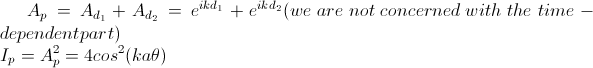
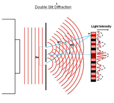
Dr. Noé then told us about how laser beams generally have a divergence of 1 milliradian, which is very close to λ /d. The talk was helpful and helped clarify the physics behind waves for me. After the "lesson" ended, I talked to the Simons/LTC scholars about LaTex.
Modeling bacterial scatter patterns using scalar diffraction theory
Since bacteria colonies are large in comparison to compared the wavelength of the light and the scattered/diffracted fields are observed in the far field, scalar diffraction theory is sufficient to model bacterial scatter patterns. [For a more rigorous model, Maxwell's equations and vector diffraction theory can be used] Scalar diffraction theory encompasses a set of theories, such as Huygens' Principle, the Rayleigh-Sommerfield theory, the Kirchoff formulation, and the angular spectrum of plane waves that are used to create diffraction models.
June 27th, 2013
Slowly, but surely I am making progress understanding the optics behind
scatter patterns. I discovered that complex
amplitude is a complex number, of the form  , where the amplitude, A, represents the magnitude and the
phase,
φ, represents the angle. The magnetic and electric fields in a light
wave are harmonic
oscillators, therefore their motion can be described by
, where the amplitude, A, represents the magnitude and the
phase,
φ, represents the angle. The magnetic and electric fields in a light
wave are harmonic
oscillators, therefore their motion can be described by 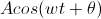 . Using Euler's
formula, you can prove that sinusoids are mathematically
equivalent to the sum
of two complex-valued functions or the real part of one of the
solutions to the equation, meaning:
. Using Euler's
formula, you can prove that sinusoids are mathematically
equivalent to the sum
of two complex-valued functions or the real part of one of the
solutions to the equation, meaning:
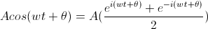
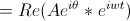
[A proof of the second term can be found here.]
Focusing on the third term, you can see where Huygen's
equation for the primary wavefront's complex amplitude, 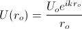 , came from. The Uo is the initial complex
amplitude of the wave, which represents the Ae(iθ) term;
the 1/ro arises from the intensity of light decreasing
as it moves away from light source by a factor of 1/r, and the
eikro term
is equivalent to the eiwt term.
, came from. The Uo is the initial complex
amplitude of the wave, which represents the Ae(iθ) term;
the 1/ro arises from the intensity of light decreasing
as it moves away from light source by a factor of 1/r, and the
eikro term
is equivalent to the eiwt term.
I am now trying to understand the wave equation for the complex amplitude of the secondary waves, which involves the Fresnel-Kirchoff diffraction formula. Dr. Noé told me that the analytical proof for the complex amplitude of the secondary waves is overly complicated and that nowadays it can be proven pretty easily numerically [meaning I don't have to memorize the proof]. I did discover that the 1+cosx in the equation is a directionality constant, which was added to account for the fact that the wavelets only move forward and not backwards.
***On a side note, I found a "diary" of sorts after Dr. Noé mentioned to me about a graduate student's interactions with Hans Bethe and Gerry Brown that is very good so far.***
June 26th, 2013
Our presentations are today. I am nervous, but also excited because I'm really interested in identifying bacteria by their elastic light scattering patterns and I also think that many of the people attending the presentations won't know much about the topic, so I will have the opportunity to introduce it to them. After talking to Dr. Noé, I decided to include a bit about the algorithms utilized by the systems. My presentation is finished, so all that's left now is to present it. I found a nice article about how to give a good presentation. I also found a quote about giving presentations, "The amateur worries about what he is going to put in his speech; the expert worries about what he is going to leave out." I am still an amateur.
The presentations went pretty well. I learned something from every one. After the presentations, Dave Battin came in and showed us a projector he owns, which was about the size of an iPhone. It was amazing to see; the colors were very vivid and whatever the image stayed in focus regardless of the distance to the imaging plane. He was able to buy the projector for only $50 on eBay.
The type of projector he was using is known as a pico projector. They are handheld projectors, which are companion devices for products such as cameras, cell phones, and tablets. The projectors are able to conveniently and quickly project the content of their companion devices on to any surface. They usually utilize either an LED or laser light source.
Moving forward my goal is to understand the optics behind bacterial scatter patterns as completely as possible.
The Huygen's-Fresnel principle is a method for solving wave propagation problems. The original OPN article I read said that the Huygen's-Fresnel property can be used to model forward scatterometry. It is a modification of the Huygens' principle which explains that the amplitude of the secondary waves fall off by a factor of cos(θ), where θ is the angle between the normals to the original and secondary waves, and the secondary waves interfere with one another according to the superposition principle. The complex amplitude of the primary wave is given by:
where k is the wavenumber, 2π/λ, and ro is the distance from the primary wave to the point source. The 1/ro arises from the intensity of light dropping off by a factor of 1/r and the kro is equal to the phase changes. I believe that eikro represents the phase modulation that the wave undergoes and Uo is the initial complex amplitude.
The complex amplitude of the secondary wave is given by the equation:
where s is the distance between Q and P, -i/λ is a constant, S represents the surface of the sphere, and K(X) is an inclination factor equal to 1/2(1+cosx). I do not yet understand this equation.
June 25th, 2013
We started off today with Dr. Noé talking about the difference between interference and diffraction in relation to interference vs. diffraction patterns; terminology usage is inconsistent. After doing some research, I think I understand both terms better now. An interference pattern is the pattern that forms when two or more waves interact producing regions of constructive and destructive interfernce. A diffraction pattern is the interference pattern that is formed when two or more waves undergo diffraction. These definitions could account for the incosistent terminology usage because by these definitions, a difraction pattern is an interference pattern, but an interference pattern isn't automatically a diffraction pattern. The relationship is a lot like that of a rectangle and a square.
Our presentations are tomorrow, so I spent the majority of today putting together my powerpoint presentation (which I will upload to my website tomorrow). I am giving a presentation on Identifying bacteria by their light scattering patterns. I am pretty confident; I know all the material and have a lot of good graphics. I really hope the presentations go well!!! I also forwarded the paper on the mathematics behind scatter patterns to Dr. Noé, so hopefully he will be able to help me make sense out of it.
June 24th, 2013
Today was the high school students' first day in the lab. It was nice meeting them. We started the day with a breakfast for all the Simons scholars in the SAC. We then showed the students and their families the LTC. William's younger siblings came and they LOVED the optics demonstrations. It was exciting to see these young kids get excited about optics and learning. The little sister even said, "Learning is fun." It was very heart-warming to hear.
For lunch, we went to the Simons Center Cafe with Marty. After which, we talked to the students about their Wednesday presentations, lab notebooks, and webpages. We crafted titles for all of the student's presentations. I decided that the title of my presentation is going to be Identifying Bacteria by Their Light Scattering Patterns. Melia talked to the students about how to use their lab notebooks and I talked to them about their webpage. It went well. I am very excited for this summer. I edited my Beginner's Guide to Linux so that it now includes a link to the DoIT page where you can download an SSH client from Stony Brook.
On a side note, after talking to a friend, I gained a little more insight into the math behind elastic light scattering, but I still have a long way to go before I truly understand it.
June 21st, 2013
I'm on the search for an image processing software, which will be able to capture the scatter patterns from bacteria. When I was trying to find information on the CCD camera we have yesterday, I stumbled across an old LTC student's project. This student mentions using Scion for their project. I checked and this image processing software is still free. The newest version is compatible with Windows 7/8/Vista. Scion Image can be used to capture, display, analyze, enhance, measure, annotate, and output images. From what I've learned so far I think it would fit my purposes. I also found a program called ImageJ, which looks like it could be useful for finding colonies and alo determing the shape of them.
I am trying to understand the math behind modelling scatter patterns right now. It is extremely complicated, but I am confident that if I go home and think about it over the weekend I will be able to make some progress.
I made a diagram of the experimental set up described in a 2009 E. Bae et. al. paper.
Papers to read: Modeling light propagation through bacterial colonies and its correlation with forward scattering patterns ; Analysis of time-resolved scattering from macroscale bacterial colonies; Label-free detection of multiple bacterial pathogens using light-scattering sensor; Automated classification of bacterial particles in flow by multiangle scatter measurement and support vector machine classifier; System Automation for a Bacterial Colony Detection and Identifcation Instrument via Forward Scattering
June 20th, 2013
Portable Bacterial Identification System Based on Elastic Light Scatter Patterns
This paper outlines the specifications of a low-cost, environmentally-friendly, portable, and speedy microbial-identification system that relies on forward-scatterometry. The final system includes a nine pound 12" x 6" x 10.5" machine, which utilizes elastic light scattering to capture bacterial colony characteristics and delivers the colonies' classifications via wireless access. The device comprises of 2 CCD cameras, a rotational and translational stage, and a 635-nm laser diode. The system employs software algorithms, such as the Hough transform, 2D geometric moments, and the traveling salesman problem to count the number of colonies and calculate their circularity, to center the colonies, and to minimize the travel time between colonies. An "in-the-field" test was conducted by using the system to identify four different types of bacteria on both pure and mixed plates in a number of locations and was found to be between 95 and 100 percent accurate. The device has possible applications in biosecurity, food safety, and monitoring and preventing nosocomial infections, hospital-acquired infections.
The Rundown
Function: counts colonies and captures the colonies' forward scattering patterns to identify them
Physics behind it: incoming wavefront interacts with microscopic features of colonies and propagate to imaging plate, providing a unique scatter pattern
Cameras
Used 2 PixeLINK PL-B741U cameras with 1280 x 1024 resolution and a 6.9 µm pixel size
Imaging lens Tauron M118FM08 with f=8mm and 34 x 25.6o viewing angle so that camera can view whole area of plate
We have an Electrim EDC1000N with 658 X 496 resolution and 7.4 µm pixel size
Forward scatterometer
Circular laser beam module λ=635 nm P=0.95mW
45 mirror
Monochrome camera
Natural-density filter to prevent saturation
Motorized stage that rotates in θ and R direction
Electroluminescent screen placed under petri dish to provide back illumination
Computer
Used a PC with a Pentium 4 processor, CPU 2.80 GHz, and 1 GB of RAM
Images sent to custom built analysis software coded in visual C#, which centers the stage and initializes the system, counting, and locating bacterial colonies
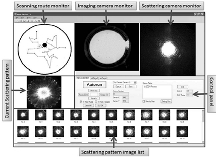
There are three basic steps to correctly identify microbes:
Sample acquisition/preparation
Microbe detection
Microbe identification
The first scatterometers required manual positioning of beam and motion control to record forward-scattering signature. This would require less programming and materials and would be easier to execute for a research project.
I've heard the term light pollution a number of times throughout the years, usually in reference to how you couldn't see the stars any longer. I wasn't really too concerned because I thought it only affected astronomers. I realize now that light pollution has been getting progressively worse and has a wide range of adverse effects on not only astronomy, but also animal and human health.
Astronomy
Light pollution is making it harder for astronomers to observe the stars. Having to contend with "sky glow", the increased brightness in the background sky caused by light pollution, Astronomers often have to observe celestial bodies for longer periods of time to reduce the noise-to-signal ratio or increasingly, travel to remote locations, like Antarctica, in order to view the celestial bodies they are studying.
Animals
I hadn't thought about how light pollution would affect living organisms; light pollution has been shown to disrupt a number of animal behaviors though, often at the expense of the animals life. Loggerhead turtles for example have evolutionarily adapted to head towards the brightest light source after hatching. Traditionally, this has been the moon and stars reflecting off the water; nowadays, it is often hotels or parking lots. The loggerhead babies journey towards the hotels and parking lots only to meet their maker in the form of a car or dehydration. Bugs also often fly into lights killing themselves in the process. This can have a negative effect on an ecosystem by disrupting the food chain. Birds have also lost their way while migrating tricked by the lights and songbirds have been known to crash into brightly lit buildings killing themselves.
Human health
Light suppresses the secretion of melatonin in humans. Melatonin has been linked to inhibiting cancer growth and inducing sleep. Light pollution also poses a hazard to drivers and also causes a higher risk of malaria because mosquitoes are attracted to the light.
***On a side note, I've noticed it has been taking longer for my journal to load, so I moved all of my spring journal entries into the spring 2013 section of my webpage. ***
June 19th, 2013
Parallax is the difference in the apparent position of an object as viewed by the right and left eye. The parallax effect can be exploited to see 3D object. In the diagram below, the far left figure illustrates the path of light from an object directly in front of you into your eyes. While the diagram in the middle, shows how your eyes perceive two pictures of an object transposed on a projection plane the same as if the object were directly in front of you; the light paths between the center crossing points and the eyes are the same as they would have been if the ball were directly in front of you. Your eye does not distinguish a difference between these two objects. To achieve a 3D image though, each eye must only see one picture of the ball meaning that the dashed lines must be blocked, while the crisscrossing paths are allowed to pass [Situation illustrated in the far right figure]. This can be achieved by blocking the dashed lines with one's hands or by wearing horse blinder glasses.
The article I was reading went on to suggest four experiments one could perform to better understand the physics behind the parallax effect.
Experiment 1: What Controls How Far the Image Pops-Out?
Make two dots of the same size in Paint or Adobe Photoshop and place them about 10 cm apart from one another
Make a pair of horse blinder glasses[A template can be found in the article]
Open the flaps on the horse blinder glasses to about 30 degrees
Adjust your distance from the computer screen until the a dot appears 'out' of the screen
Gradually increase the distance of separation between the two dots; you should observe the image of the dot moving towards you until a point where the effect ceases
Looking at the diagram below, it is apparent that the farther apart the two dots are, the closer to you eyes the point of intersection between the two light paths become, thereby making the image of the object appear closer.
Experiment 2: Creating a 3D Image from the Left & Right Views of an Object
In order to create a 3D effect, the right and left view of a scene must be transposed on top of one another.
Take a picture of a scene
Move 30cm to the left and take a picture of the same scene
Place the two pictures side by side in an image editing program
Put on horse blinder glasses and observe as the images become 3D. [As an alternative, you can cross your eyes until you see four images and then slowly uncross them until you only see three images, focus on the middle image and it should appear 3D.]
Experiment 3: Encryption
View encrypted image[like one below] with horse blinder glasses
One aspect of the picture should jump out at you [In the picture I provided, it's JFK's birthplace.]
Experiment 4: Converting Your Laptop Computer into a 3D Display
As always, the best was saved for last. In this experiment, you will create a 3D display using polarized light. In order to complete this experiment, you will need:
A source of polarized light, such as the liquid crystal display of a laptop computer [The light from liquid crystal displays are already linearly polarized]
Two polarizer sheets
Clear cellophane, 25-microns thick, such as the kind used to gift wrap baskets [Cellophane is birefringent]
A stereoscopic pair of images (left and right view of image)
In this experiment, the polarization direction of light is rotated 90o away from the polarization direction of the other half of the screen. A crisscross between the paths of light can be created by wearing polarizer glasses with the polarization direction of each lens varying by 90o.
First orient the polarizers so that their directions of polarization are perpendicular to one another [You will be able to tell because almost no light will be transmitted].
Insert the cellophane sheet between the two polarizers and rotate ONLY the cellophane sheet; observe the variations in the intensity of light transmitted [If the light intensity does not vary, try another brand of cellophane]
Find the orientation of the cellophane at which the transmitted light is minimized; mark a line on the polarizer so that you remember the protrusion direction
Determine the direction of the polarization of light from the liquid crystal display by holding one of the polarizers in front of the screen and rotating it until you find maximum transmission
Cover the right half of the screen with cellophane oriented so that the protrusion marker is at a 45o angle to the direction of polarization of the screen
Make your own polarizer glasses by matching the polarizer for the left eye to the polarizer covering the right side of the screen and the polarizer for the right eye to the polarizer covering the left side of the screen.
Display the stereoscopic image on your computer screen and watch as the image becomes 3D
Interested in learning more? Check out the links below:
We had a really nice pizza lunch today: the LTC group, Marty, James, and Seth. It was interesting to hear a little about what people were working on or interested in. We talked about secondary education, college, grad school, and which field of physics to go into. It was helpful for me to hear about other people's journey's through college and it helped me get to know everyone a little better.
I found a nice quote by David Mermin today:
My complete answer to the late 19th century question "what is electrodynamics trying to tell us?" would simply be this: Fields in empty space have physical reality; the medium that supports them does not.
Having thus removed the mystery from electrodynamics, let me immediately do the same for quantum mechanics: Correlations have physical reality; that which they correlate, does not.
June 18th, 2013
I created A Beginner's Guide to Linux today. It isn't an all-encompassing guide, but it includes many of the commands that I use on a day-to-day basis and think will be useful to the high school students working in the LTC this summer.
Dr Noé suggested that I read an article in the June 2013 edition of Physics Today on water in the atmosphere. Although, water only makes up 0.25% of the atmosphere, it plays a big role in determining how the Sun's energy is distributed through the atmosphere and across Earth's surface and the character of large-scale circulations. Water is so influential because of its unique physical and radiative properties; it is effective at interacting with radiation throughout most of the IR spectrum, which makes water the most important absorber of solar radiation in the lower atmosphere and its radiative effects also power the hydrological cycle. These properties make understanding water fundamental to understanding the atmosphere and climate. The authors of the paper argued that given the known properties of water, previous studies have overestimated the warming Earth will experience as a result of atmospheric CO2 doubling, the climate sensitivity. They believe that much of what we don't understand about the climate and the atmosphere is linked to what we don't yet understand about water. In a separate article by the same authors published in Science magazine, they argue that the climate community has not given water its due diligence. They believe that inaccuracies in climate models can be reduced by better understanding the role of water in the atmosphere in phenomena like cloud formation, moist convection, and mixing.
June 17th, 2013
I read a paper entitled LaTex for the Horrified by Paul Brna today. [I was unable to find the document online] From talking to upperclassmen, it seems like LaTex is a good program to know. They have used LaTex to write lab reports, theses, and other papers for school. Therefore, I have compiled a page about formatting in LaTex.
I was reading more about labeling fruits and vegetables using low powered lasers, when I stumbled across the website for a company called Best. Best is a Norwegian-based company that uses the latest and most advanced in optical technologies to sort different products and materials across a number of industries. They employ a number of technologies to find defective and foreign objects within a product, including: Advanced Forign Material Detection (AMFD), cameras, lasers (detox, fluo, and shortwave infrared [SWIR]), Rear Ejection System [RES], hyperspectral, Hyperion, and X-rays.
Advanced Foreign Material Detector (AMFD)- designed for the detection of defects and foreign material that are often difficult to find because of similar structure or color characteristics; currently used in raisin and nut industry currently; potential to be used in any food industry
Cameras- Best has developed a high resolution camera with adapted spectrum; works in the visible, infrared, ultra violet, and other spectrum; multiple cameras can be placed at different angles to scan the product from many sides; has shape recognition; can differentiate between water and non-water based products; used for food and non-food applications (French fries, shrimp, vegetable, snacks, raw cotton, and plastics)
Hyperspectral- recognizes the scattering pattern of each type of produce and will remove anything without the target scattering pattern; measures different spectra; removes discolored, deformed, or foreign items; mainly used in food industry
Lasers- Best's most effective technology for maintaining product quality; able to sort based on color, structure, size, shape, chlorophyll content, water content, and biological characteristics
Detox- able to detect Aflatoxin, a highly-toxic substance, in nuts and dried fruits and remove the toxin; relies on on aflatoxin's distinctive scattering pattern to identify and remove it
Fluo- provides better contrast to detect color and texture differences in products with fluorescence features; can sort products with chlorophyll (peas, green beans, spinach) from those without (wood, plastic, glass)
Shortwave Infrared (SWIR)- range of wavelength in infrared used to detect water content of objects; used for frozen fruits and vegetables
Rear Ejection System (RES)- detects heavy/aerodynamic defects (in glass, stone, etc) with high efficiency
Hyperion- sorts objects based on full featured object analysis; can simultaneously evaluate the importance of a spot with respect to the total area; fast and versatile
X-rays- able to detect defects based on density differences; used on packaged products (nuts, canned vegetables and fruits); can be used to detect pits in cherries and olives
The research Best is doing is similar to many of the possible research project ideas I have come up with, in that the both are looking to create optical technologies with the capabilities of catergorizing things (elastic light scattering to identify bacteria, laser labeling, cartenoid-level detectors). I find the work Best is doing to be both interesting and innovative and I would be very interested in applying for a job at TOMRA (Best's mother company) after I finish my schooling.
June 14th, 2013
Elastic Light Scattering for Identification: A Summary
Introduction
Food contamination poses a serious threat to America, both to public health and to food companies that stand to lose millions of dollars. According to the Center for Disease Control, food-borne illnesses cause 300,000 hospitalizations and 5,000 deaths annually. Food-borne illness outbreaks also cost American industry about $7,000,000,000 in loses annually. The recall costs to food manufacturers include getting food off the shelves, lawsuits, revamping plants, and repairing public relations, which can very easily cost in the millions of dollars. Recall costs also don't take into consideration the cost of a tainted reputation and the loss of sales, which can often be hard to monetize, but which can devastate a company. As a result, the food and healthcare industry are constantly searching for better methods to rapidly and cost-effectively detect and identify pathogenic microorganisms.
There are three main methods of detecting pathogenic microorganisms currently employed: biochemical identification, genetic tools (such as PCR and DNA fingerprinting), and spectral analysis (such as mass spectroscopy). While these methods are an obvious step-up from their predecessors, they are by no means the pinnacle of pathogenic microorganism detection. These methods can be slow, costly, and can require growth of the sample before testing. Elastic light scattering, ELS, is advantageous because it is cheap, quick, and requires a small sample size. Unlike the other methods, it is also quantitative. While the currently popular methods result in only a positive or negative result, elastic light scattering can provide us with a quantitative result as to how densely populated the pathogenic microorganism is within the sample. Below is a table comparing the features of ELS to the current popular methods.
Elastic Light Scattering as a Means of Identification
Scattering occurs when a beam of particles or radiation deviates from its straight line trajectory as a result of the interactions between the beam and localized non-uniformities; elastic scattering is when the incoming and outgoing wavelengths are identical. Elastic light scattering identifies pathogenic microorganisms by encoding the micro- and macro- morphology of a colony onto an interrogating wavefront. The optical signal encoded within the wavefront is then decoded by examining the forward-scattering pattern that results as the wave front propagates towards the far field. When the altered wavefront reaches the imaging plane, the characteristic scattering pattern is generated via spatial interference. As the photon travels from the top to bottom of the colony, the interactions that occur through the z-depth accumulate and alter the amplitude and phase of the photon. The way in which the colony influences the photon is dependent on refractive indices, the local density of the colony, and shape.
Each microorganism has a distinct scattering pattern which is essentially unique due to each organism's unique biochemical nature and structure. Past research has proven light scattering signatures from colonies to be reproducible and differentiable without losing their uniqueness. This makes elastic light scattering an ideal method for pathogenic microorganism identification.
A Little Bit of Math
Before the wavefront interacts with the colony, its spatial distribution is a characteristic of a plane wave with typical Gaussian intensity distribution. After the photon-colony interactions, the wavefront is encoded with a different amplitude and phased modulation in 2-D space. Applying the Huygens-Fresnel principle you can model the process using

where where x_i,y_i are points in the image plane, sigma denotes the colony surface, t(x_a,y_a) is the 2-D transmission coefficient, E_1(x_a,y_a) is the 2-D incident Gaussian beam, phi(x_a,y_a) is the 2-D phase-modulation factor, r_ai is the distance from aperture plane to image plane, lamda is the wavelength and theta is the angle of r_ai to the optical axis.
ELS equipment
The equipment required to perform ELS microorganism identification has two main components: the plate reader and the forward scatterometer. The plate reader ascertains the spatial distribution of the colonies by measuring the light transmitted from an LED light. The location and individual characteristics of the colony can then be extracted from this data using image-processing algorithms. After the colonies have been located, the plate is then transferred to a forward scatterometer for laser probing [Past research has utilized a 635-nm with a 1/e^2 of 1mm laser beam]. The laser beam is sent through each colony and its associated scattering pattern is captured.
There are two issues that need to be addressed solved before this system can be implemented: the number of colonies on a plate usually ranges from 50-200 and the scattering pattern is generated by comparing the relative position of the laser and the colony, therefore the circularly symmetric scattering pattern is optimized when the position of the center of the colony is close to the center of the laser beam. In order to be time- and energy-efficient with multiple colonies on one plate, a trajectory optimization technique must be employed to minimize the amount of time spent traveling between two colonies. In order to center the colony with the center of the laser, 2D centering can be performed by calculating the geometric centroid of a scattering pattern relative to the imaging frame.
I was able to find a video online of a group that developed a mini ELS microorganism identification machine.
The Final Verdict
ELS offers scientists a cost-effective, quick, and reliable method to identify pathogenic microorganisms. ELS is capable of identifying organisms without additional biochemical tests, which could reduce costs of identification. ELS is also faster than any other method on the market right now. There are still some mountains ELS needs to overcome.
ELS only works for colonies that are close to transparent and approximately the size of the laser beam and for organisms that are culturable. At this point in time, research has only been done on bacteria. In order to maximize efficiency, databases of scattering patterns must be compiled. ELS has also come under fire because some argue that the differences between scattering patterns can be minute and indistinguishable.
If I were to do a project where we used elastic light scattering to identify different microorganisms, it would probably only be practical for me to do it by identifying one colony at a time; this means no trajectory optimization technique. This could be possible by trapping a single cell or colony in an optical vortex and then imaging it. Figuring out how to match up the center of the laser and the colony could also prove a problem.
References
Robinson, J.p., B.p. Rajwa, E. Bae, V. Patsekin, A.m. Roumani, A.k. Bhunia, J.e. Dietz, V.j. Davisson, M.m. Dundar, J. Thomas, and E.d. Hirleman. "Using Scattering to Identify Bacterial Pathogens." Optics and Photonics News 22.10 (2011): 20-27. Print.
McGrath, Jane. "10 Costly Food Recalls" 12 March 2009. HowStuffWorks.com. http://www.howstuffworks.com/10-food-recalls.htm 14 June 2013.
Bloggs, Bill. Baby Bugbuster Project. 2011. Video. YoutubeWeb. 14 Jun 2013. http://www.youtube.com/watch?v=kDgh2xoEWIw.
June 13th, 2013
Dr. Metcalf gave the second part of his talk on entanglement today. He started off the talk by showing us a speech given by Joseph Eberly entitled, "When Malus Tangles with Euclid Who Wins?". In the talk, Dr. Eberly used the Bell inequalities to showcase the differences between classical and quantum systems. In classical systems, the Bell inequalities hold; Dr. Eberly demonstrated this using the probability of a penny, dime, and nickle landing on heads or tails. The following equation is an example of a Bell inequality. [The uppercase letters represent a heads while the lowercase letters represent a tails.]

Dr. Eberly then proved that after a sufficient number of trials this inequality will always hold true as demonstrated in the equations below.


The probability of any of the three above
situations occurring is equal to 1/8, therefore the Bell inequality
will be satisfied after a sufficient number of trials because  . Flipping coins represents a classical
system and so the Bell inequalities hold.
. Flipping coins represents a classical
system and so the Bell inequalities hold.
Eberly then explained that the Bell inequality can be violated by quantum systems. He showed this using the example of a photon polarization experiment using a Clauser inferometer (pictured below).
When you write the Bell inequality for this example, you get  . This equation can be simplified down
using
trigonometric relations and the situation to get
. This equation can be simplified down
using
trigonometric relations and the situation to get  . By plugging in π/8 into the
inequality, (
. By plugging in π/8 into the
inequality, ( )
you can see that the inequality is violated. This violation of the
Bell inequalities arises from the fact that the Bell inequality
is defined for systems where there only exist specific states. In
our example though, the polarization state does not exist if we do
not observe it therefore our example contains superposition states,
or limbo states, where the photons are in both polarization states.
)
you can see that the inequality is violated. This violation of the
Bell inequalities arises from the fact that the Bell inequality
is defined for systems where there only exist specific states. In
our example though, the polarization state does not exist if we do
not observe it therefore our example contains superposition states,
or limbo states, where the photons are in both polarization states.
After the video, Dr. Metcalf went on to explain entanglement to us. Entanglement seems to a relationship between seemingly unrelated variables. With entanglement, if you know the value for one entangled variable, you know the value for the other entangled variable. He showed us an example of entanglement involving an atom and circularly polarized light. In his example, there existed a connection between the motion of the atom and the atom's original internal state. By knowing the motion of the atom, you could deduce the polarization of the absorbed light and the original internal state of the atom. Hopefully this graphic will clarify what I cannot.
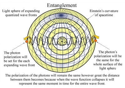
Laser Labels for Fruits and Vegetables
The current method for tracking and identifying tainted fruits and vegetables is to use stickers. Stickers pose a problem though because they can fall off and can leave a sticky residue on the outside of the produce. Lasers hold the answer. Physicists have created a system which labels produce using an infrared laser to label onto produce its variety, price code, and where it was grown. The whole process only takes about 25 milliseconds and has proven safe. Sunkist is one of the first companies to adopt this new technology, purchasing the rights to it for their citrus products.
Lasers That Can Tell If You've Been Eating Your Fruits and Vegetables
Up until this point measuring biomarkers has often relied on obtaining blood, urine, or skin samples. Obtaining these samples can be painful, costly, cumbersome, and can sometimes expose the body to pathogenic organisms. Scientists have created a device which measures the cartenoid levels in the blood by bouncing a blue laser light off of the skin and using resonance Raman spectroscopy, RRS, to analyze the data. RRS works by measuring the changes in the energy levels of electrons in molecules after they have been excited. Cartenoids are an ideal subject for RRS because the compounds resonate very strongly and uniquely at a certain wavelength of light, which is uncharacteristic of the other compounds found in skin. The whole process takes about one minute and is completely painless.
This technology is the brain child of a nutritional epidemiologist and a laser physicist [a good example of how the lines between different disciplines of sciences are becoming increasingly fuzzy]. It has been known for decades that people that eat a high vegetable diet tend to have a yellowish tint in their skin that is particularly pronounced in their palms due to the build up of cartenoids. The device they have created take advantage of this fact. The device consists of a flexible fiber optic probe connected to a boxlike central machine. Their data so far has corresponded very well with cartenoid levels measured by serum and skin biopsy and with data collected from dietary self-report. The next step is to determine the half-life of cartenoid in the body and discover how changes in the diet affect cartenoid levels.
June 12th, 2013
Today was really exciting; there was a talk organized by Eden, a tour of Eden's lab, and a pizza lunch followed by a talk given by Dr. Metcalf.
The talk organized by Eden was given by Dr. Sotir Chervenkov, a scientist from the Max Planck Institute who is currently researching the production of ultracold polyatomic molecules. The motivations behind his group's research are to gain a better understanding of how molecules interact at low temperatures (essential to understanding molecule interactactions in space), more accurately measure the magnetic dipole moment, study fundamental physics, and eventually reach quantum degenerate regimes. His group was employing three different methods to cool the molecules with the end goal of devising a system combined all three and cooled the molecules to extremely cold temperatures. Up to this point, they have been able to cool the molecules to milli-Kelvins.
Eden's lab was quite impressive. I hadn't realized that his research deals with quantum computing. After reading his website, I now realize that he is the head of the Quantum Information Technology Group at Stony Brook. His lab hopes find the quantum equivalents of the computer elements (logic gates, bits) we have now, which obey the laws of classical physics. Their first goal is to find a way to collect the information and then find a way to store said information. Below is a graphic illustrating the differences between bits and qubits, their quantum equivalents.
Dr. Metcalf gave the "first half" of his talk on entanglement today. His talk mostly just set the stage and put us in the right mind set for his talk on entanglement tomorrow. He is also going to show us a movie on entanglement tomorrow. Dr. Metcalf explained that Schroedinger believed that entanglement is the heart of quantum mechanics; it is what distinguishes between a classical and quantum system. Dr. Metcalf explained that common sense is a set of information that we acquire from growing up in a classical world, therefore quantum mechanics fundamentally defies common sense. Superposition states violate intuition because there is no classical analog. Quantum mechanics is better viewed as a highly theoretical and mathematical concept.
[Dr. Metcalf mentioned David Mermin in passing today. David Mermin is a great writer and I would highly suggest perusing his Reference Frame column for Physics Today.]
Bruise Detection on Tomatoes Based on the Light Scattering Image
If you've ever eaten a bruised tomato, you know that the quality is significantly reduced when bruised. Detecting bruises on tomatoes can often be difficult though because the changes in coloration are often tiny. Reducing bruising in the fruit and vegetable industries could have annual paybacks in the billions of dollars; it would also increase food safety by reducing the potential for microbial infestation.
This paper elaborated how one research group analyzed light scattering images from tomatoes to detect bruised tomatoes from unbruised ones with a 90% success rate; they did find however that accuracy was affected by the age of the tomatoes. Because the optical properties of biological tissue are dependent on the morphology of the tissue, when cell walls and membranes are broken down in the bruising process this causes the scattering [light scattering is when a portion of the radiation incident on a object is scattered back to the surface of incident and leaves the object near the point of incidence] properties of the produce to change.
June 11th, 2013
I created an ideas page today to keep track of possible research topics. I also updated my journal and read a number of papers on elastic light scattering.
Scattering
Scattering is the interaction between radiation and localized non-uniformities that causes radiation (such as light) to deviate from its straight trajectory. [Interestingly, reflections that undergo scattering are called diffuse reflections and unscattered reflections are called specular.] If I were to shine a red laser on yeast, I believe it would undergo Thomson scattering. Thomson scattering occurs when light is elastically scattered by charged particles. Elastic scattering occurs when the incoming and outgoing wavelength are identical.
Bacteria Size Determination by Elastic Light Scattering
Light scattering offers an in-situ method for identifying bacteria that could identify bacteria based on their size and shape. This method is advantageous to past methods of bacteria identification because the specimen does not have to be isolated and grown before being tested. "'The characteristic of each distinct microorganism that scatters is an essentially unique scattering pattern' due to the distinct biochemical nature and structure of each microorganism." It has been proven that the Rayleigh-Gans theory agrees with experimental values for the angular distribution of scattered light from bacteria. Forward scattering from cell suspensions has also been used to correlate internal structures and scattering properties. The angular and wavelength distribution of scattered light from bacteria is heavily dependent on its size and shape. Light scattering could advance society's ability to monitor the environment for microbial contamination, rapidly respond to biological contamination, and prevent the spread of disease.
Investigation of the Presence of Rod-Shaped Bacteria on Food Surface via Elastic Light Scattering
Our food supply is highly suspceptible to contamination from pathogenic microorganisms due to the way it is grown and processed. Contamination poses a risk to public health and agricultural companies that could stand to lose in the millions of dollars from food recalls. Food and healthcare industries are searching for methods to rapidly detect and identify pathogenic bacteria. Some methods that are currently being employed are: real-time PCR, recirculating immunomagnetic separation coupled with real-time PCR, standard culture methods, piezoelectric-excited millimeter-size cantilever, light scattering, Fourier transformed infrared spectroscopy, and Raman spectroscopy. These methods still leave much to be desired though.
Light scattering has been used for feature detection and identification because of its speed and accuracy. This method utilizes lasers to generate transmission and differentiate reflection signals from the incoming beam depending on the shape, thickness, or color of the sample being tested. Angle-resolved backscattering has been used to identify microcolonies of bacteria in flow by matching their known surface textures. Light scattering signatures from colonies have been proven to be reproducible and differentiable without losing their uniqueness. Currently, most of the optics-based quality control produce undergoes tests the firmness or sugar content using a single wavelength.
This study sought to investigate the presence and noise-to-signal ratio of rod-shaped bacteria (E. coli) on the surface of produce (tomato) using elastic scattering. The researchers found that the light component parallel to the plane of incidence's polarization was less sensitive to the background noise as the incident angle increased; while the perpendicular portion of the light's polarization became more sensitive to background noise as the incident angle increased. They were able to use elastic scattering to detect the presence of rod-shaped bacteria.
Elastic Light Scattering from Single Cells: Orientational Dynamics in Optical Trap
A complex spatial pattern is formed by a cell, which is dependent on the cell's size, shape, index of refraction, density, and morphology. Elastic light scattering may offer us more information on a cell's morphology than incoherent techniques (ex. fluorescence spectroscopy). Studying the scattered light from a cell at a number of different angles can reveal information about the cell's morphology. The ability to differentiate between minute differences in morphology could be used in the future to differeniate between different cell states.
In this experiment, the researchers were able to record light scattering patterns from three different types of bacteria. Their setup was subject to currents in the medium they were using causing distortions in the wavefront, the orientation of the cell to change, and at great enough depths even made it impossible to trap a single cell. The authors suggest that a follow up experiment be conducted in which multiple lasers are used to illuminate the cell from different directions so that the orientational dependence is averaged out and the accuracy of the light-scattering measurements is increased.
I also learned a very useful command today for Linux ctrl+ins-copy; shift+ins-paste [To the best of my knowledge, this command only works on PCs]
June 10th, 2013
Today was our first day as a real group. I had the pleasure of meeting Melia today and it was nice to see Casey again. I spent the majority of the morning today updating my journal because my computer sadly broke on Sunday. For lunch, we joined Dr. Metcalf's research group and Marty Cohen. It was nice to meet some other students who will be working here over the summer.
After lunch, we attended a talk organized by Eden on creating elementary quantum networks out of single atoms in optical cavities. The goal of the researcher's lab was to build quantum networks. Ideally this network would be composed of many identical nodes, so that any node is capable of doing any job it is tasked with, connected by quantum links. Quantum networks could have applications in quantum communication, quantum cryptography, and quantum networks between quantum computers.
Melia and I had dinner with Dr. Noé at Mirabelle Tavern today and talked about the summer, physics, and life in general. It was a lot of fun!
June 7th, 2013
Today is the last day of our "spring cleaning". I learned a lot about the lab and the instruments in it during our cleaning. I'm excited to meet Melia and see the other undergrads again on Monday. I read an article in OPN today on using elastic light scattering to identify bacterial pathogens that really interested me. I would definitely be interested in doing a project involving using elastic light scattering to identify "bacteria" because it would marry my love of biology, microscopy, and physics.
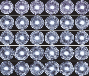
The diagram above on the left shows how photon-colony interactions change the wavefront characteristics. The picture on the right shows the ELS pattern from 30 different Listeria innocua colonies.
June 6th, 2013
Today was very exciting because I got to take apart an old projector. I had never taken a machine apart before today and found it really interesting to see the insides of the projector. The projector we took apart was a Sharp Thin Film Transistor Active Matrix Liquid Crystal Projector XG-2000U. Below is a diagram of how I think the light traveled through the projector.
In order for the projector to work:
-
There would have to be three different paths the light follows (one for each of the primary colors: red, blue, and yellow)
-
Each path would travel through only one lcd and lens
-
The paths would have to obey the laws of reflection and transmission.
June 5th, 2013
Dr. Noé and I had a long late lunch-early dinner at Mario's today, in anticipation of a planned late afternoon power outage that never took place, which gave us time to discuss a number of different physics topics. The first topic we discussed was why the periodic table looks the way it does.
The Periodic Table from a Physicist's Standpoint
The first thing we discussed is principal quantum number, N, which can be any positive integer. We then discussed orbital quantum numbers, ℓ, which have the values of 0 through N-1. Next, we talked about magnetic quantum numbers, m, which is the set of integers from -ℓ to +ℓ with 2ℓ+1 possible values. For each magnetic quantum number, there are also two spin quantum numbers, which arise from there being both an up and down spin for electrons. No two electrons can have identical quantum numbers as dictated by the Pauli Exclusion Principle.
From the diagram, you can see that for N=1, there is a maximum of 2 possible electrons. Looking at the periodic table, you can see that in the first row there are two elements, which corresponds to the maximum number of electrons when N=1. As you progress down the periodic table, it is important to note that the number of elements in a row corresponds to the maximum number of electrons for a given principal quantum state. When l=1 that corresponds to the s(sharp) shell; when l=1, it corresponds to the p(principal) shell; when l=2, it corresponds to the d(diffuse shell; lastly, when l=3, it corresponds to the f(fundamental) shell.
Adaptive optics is a technology which allows machines to correct for nonhomogenity in real-time. Adaptive optics works by measuring the distortions in a wavefront and then correcting for said distortions. Adaptive optics is used in astronomical telescopes to correct for distortions in the atmosphere, microscopy, optical fabrication, and retinal imaging.
We also talked about singular optics, which is the study of optical vortices (also known as phase singularities) and complex light. Dr. Noé also talked to me about Michael Berry, one of the "fathers of singular optics". Complex light is a newer area of study, which I still am a little unclear on. It seems like the term is semi-superficial at this point and there is no common thread running between the different research projects. Dr Noé also told me about a past LTC student, Maanit, who wrote a program to find the intensity peak caused by coherent back scattering. After talking to Dr. Noé, I have many more ideas for possible project ideas.
June 4th, 2013
I read another OPN today and came across some more idea for projects.
Ideally, a Bessel beam is a non-diffracting light beam with an infinite number of rings that covers an infinite distance and requires an infinite amount of power. In reality, scientists can only approximate Bessel beams. (Researchers can create quasi-Bessel beams which are very similar to the theoretical ideal.) Bessel beams are capable of self-healing meaning the beam can be partially obstructed at one point, but will reform at a point further down the beam axis. Bessel beams have been around since the late nineteen-eighties and have a number of applications, including optical tweezers and precision drills; researchers are looking into the possibility of using Bessel beams to transfer information.
Airy beams are light beams that transversely accelerate as they travel. The intensity peaks of these beams follow parabolic trajectories, much like the ballistics of projectiles. Due to their shape-preserving character, Airy beams are "self-healing" like Bessel beams, which has useful applications in turbulent and turbid systems. Some applications of thee beams are: particle and cell micromanipulation, laser micromachining, light-induced curved plasma channels, self-bending electron beams, and accelerating plasmons.
Dr. Noé and I had gelato for dessert. After ordering, I asked Dr. Noé if he knew how gelato was made; he did not and challenged me to find out how gelato is made.
June 3rd, 2013
Today marks the beginning of my summer research in the Laser Teaching Center. Dr Noé was a couple minutes late arriving to the lab, which worked out well for me because it gave me a chance to browse an OPN magazine. An article on optical vortices and another on edible lasers stood out.
Optical vortices are points of zero intensity within an optical field. In an optical vortex, light twists around its axis of travel like a corkscrew; extinction occurs at the axis. The article mentioned the some applications of vortices: synthetic aperture radar, electron microscopy, adaptive optics, and phase unwrapping. I would be interested in looking further into the applications of optical vortices as a possible project topic.
The laser that was the inspiration for this article wasn't truly edible (The laser was made out of a clear, unflavored gelatin and sodium fluorescein dye, which the author describes as "almost non-toxic".). The author however does speculate on a number of ways edible lasers could be created.
-Dyed lasers-If the laser made use of a dye, the dye would have to be nontoxic, soluble, and lasable in ethanol, so that in principle they could be drank. Just a droplet of the alcohol containing dye would by itself constitute an ideal laser. The author suggests that if you were to try to create an edible laser in this way (although, he does not endorse eating the laser), sodium fluorescein, coumarin, and sulforhodamines would be good dyes to start with because they tend to be less toxic.
-Salty lasers-A laser could also be created using lasing defects in crystal lattices, such as potassium chloride or sodium chloride. The author also speculates that lasing defects or impurity centers may also be present in rock candy or crystallized protein, which could allow those mediums to become lasable.
-Liquid lasers-The author notes that lasers can be made out of ethyl and methyl alcohol. Lasers can be made out of vodka, gin, and rum, but only lase on one line and lase rather weakly when compared to methyl alcohol.
Further Reading:
-"Laser Action of Dyes in Gelatin"
-"Edible Lasers and Other Deligts of the 1970's"
I mentioned "bubblegrams" to Dr Noé and he suggested that finding a novel way to measure the size of the bubbles within the crystal as a possible project idea.