Creating Bessel beams with a 4-f spatial filter
Introduction
In this project, we explored the properties and a few basic applications
of non-diffracting and self-reconstructing Bessel beams. We then used a
recently described 4-f spatial filtering method [1] to generate a
Bessel-like beam that had a central core diameter of less than 45 microns
which persisted over a distance of 47 mm.
Bessel beam overview
Bessel beams are a non-diffracting solution to the Helmholtz wave equation. They are characterized by their very intense, infinitely long, narrow core, which is surrounded by lesser intense concentric rings. This core is especially impressive when compared to a Gaussian beam, whose beam waist would spread rapidly as it propagates if it were to start off at the same narrow size.
Due to the finite dimensions of our optical elements, we cannot create an ideal Bessel beam. But it is possible to make an approximation beam that maintains a constant core size over a finite distance before exhibiting a slower rate of diffraction. In fact, Bessel beam approximations have been employed in conventional optical scanners since the early 1990’s to extend the working range of the device [2]. Even in this mass-produced form, the beam’s core is able to resolve barcodes at distances three times farther than a Gaussian beam could.
Geometrically we can picture the Bessel beam as a uniform superposition of
plane waves whose wave vectors lie on the surface of a cone. The
constructive and destructive interference of these waves creates an
intense core with a plurality of concentric rings that continually feed
lost energy back into the center. This explains how the beam is able to
remain diffraction-free and even self-reconstruct around obstacles.
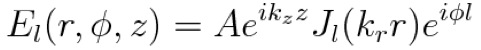
Mathematically we can quantify the beam’s electric field amplitude with an
equation that’s proportional to a Bessel function in cylindrical
coordinates.
Creating a thin ring of light
One way of creating these beams is by uniformly illuminating an annular aperture to create a thin ring light source, because the Fresnel diffraction of this thin ring of light creates a Bessel-like beam. This was first tried by Durnin and Eberly in 1987 with a 10 micron wide aperture [3]. By collimating the rays that emerged from this aperture, they were able to create a beam with a constant intensity on axis over a certain distance
Another way of creating a thin ring of light is by spatially filtering the
diffraction pattern of a circular aperture. As discovered in our pinhole
diffraction mini project, we can filter out the lower spatial
frequencies to create an edge-enhanced image of this circular aperture.
This can be done with a 4-f spatial filtering setup.
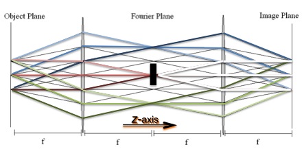
A lens placed one focal length away from an illuminated OBJ collects and
organizes the different rays being diffracted at the same angle into a
diffraction pattern in the Fourier plane. So we can place a filter here
to modify the description of the object in terms of its spatial
frequencies, and a second lens will image the object based on how the
diffraction pattern in the Fourier plane had been altered.
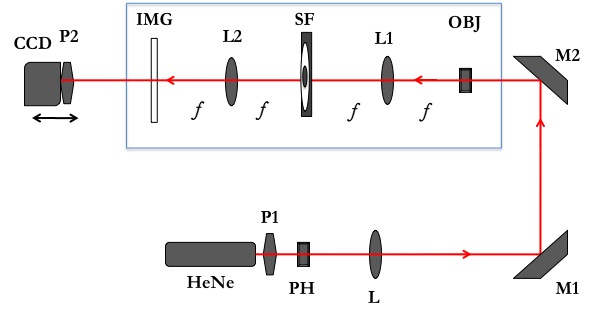
In our setup, a red HeNe laser beam was first sent through a 150 micron pinhole PH to improve the quality. A couple of polarizers (P1 and P2) were used to attenuate the beam and avoid saturation of the CCD camera. In the 4-f section, our OBJ was a 1 mm clean circular aperture, and we used two identical 40 mm diameter achromat lenses (L1 and L2) which had focal lengths of 333 mm.
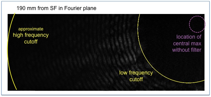
Spatial filtering
The spatial filter was a uniform 6 mm diameter black circle photo copied onto transparency paper, surrounded by an iris diaphragm closed down to 20 mm in diameter. Even though we were creating an edge-enhanced image of the circular aperture, the limit on the number of high spatial frequencies that can pass was very important.
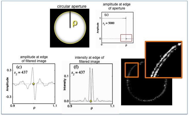
It goes back to the fact that with an aperture of radius rho, there’s
always a Gibb’s overshoot at the edge. And because of this Gibb’s
overshoot, there’s a point where the amplitude crosses the x-axis. In the
image plane, this translates to a zero in the middle of the diffracted
field at this radial point, and we end up with a ring that has a
double-lobed intensity profile.
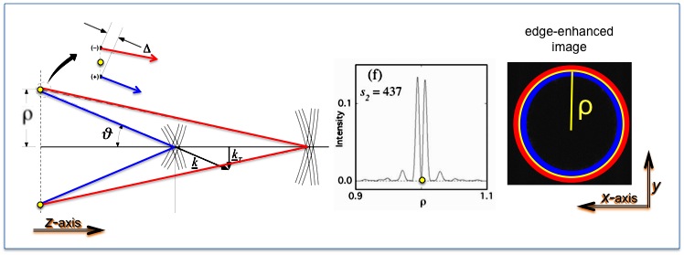
This means that there’s a propagation delay between the two lobes of the
amplitude: the inner lobe intersects with optical axis sooner than the
outer lobe. But this is desirable because as you move down the z-axis,
the lobes diverge and create a zone of constructive interference on axis
where the Bessel-like beam forms. Then, at a certain point once they’ve
diverged too much, they destructively interfere on axis and the
Bessel-like beam disappears. But the propagation delay is important,
because otherwise the lobes would destructively interfere from the start.
So by limiting the high spatial frequencies, we’re limiting the Gibb’s overshoot, which means the amplitude lobes will be more distinct and well separated. There will be a longer propagation delay between them, which means a larger zone of constructive interference on axis, and basically it creates a chain reaction, which results in a longer Bessel-like beam.
Recording the Bessel beam
We used an Electrim EDC 1000N camera, which had 7.4 micron pixels, to take transverse images of the beam. As mentioned earlier, there were two polarizer’s in place: one polarizer was attached directly to the camera, while a variable one was placed in front of the laser to attenuate the beam enough for preventing saturation in the photos.
We took a series of images from the OBJ through the 4-f setup and beyond
to: (a) image the Fresnel diffraction zone between the object and first
lens, (b) image the Airy pattern between the first lens and spatial
filter, and (c) illustrate the effect of using an annular filter by taking
photos behind the Fourier plane with and (d) without it in place. The
distance between the OBJ aperture and the first lens was subject to
Fresnel diffraction. Since the lens was placed one focal length away from
the aperture, we then were moved into the Fraunhofer diffraction regime
where the classic Airy pattern was observed. This continued through the
spatial filter to the second lens. Then after the second lens, we were
back in the Fresnel zone: the light rays converged towards the focal point
in the reversed way that they converged originally from the OBJ aperture
to the first lens. After they come to a focus to form the thin ring, they
started to diverge again, in a mirrored process.
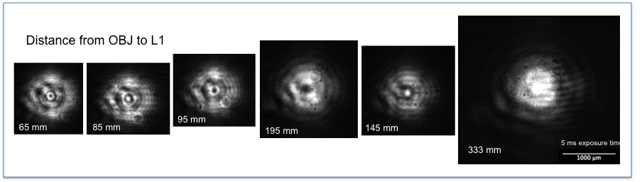
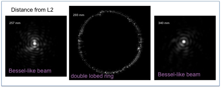
After looking through the sequence of images I had taken of the evolution of the Bessel beam, I marked out the distances where the beam formed and where the rays were focused into a ring. The first beam started forming (as in, there was a central core with concentric rings visible) at about 220 mm behind L2 and dissipated (when there is no longer a clear central core) at a little fewer than 270 mm. The ring of light came into focus at 293 mm. Then the second Bessel beam started at about 320 mm and ended at a little under 370 mm. The processes were mirror images of each other! We assume this was to be expected with ray geometry, however it was still interesting to have calculated with the experimental results.
Analysis with ImageJ
Using ImageJ, we figured out how to make an animated gif by stringing
together a series of images of the Bessel beam evolving from the
double-lobed ring of light. On each image of the animation we included
both a 1000 micron scale and the distance that it was taken from the final
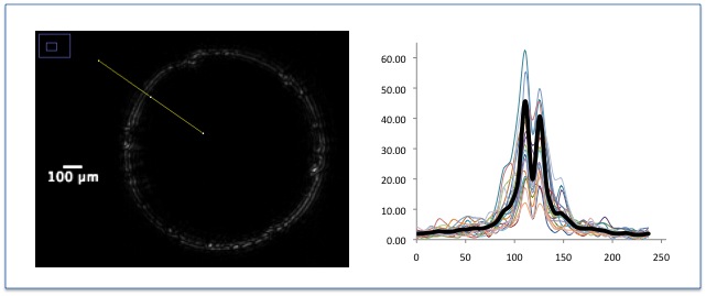
lens in my setup. We then worked on creating an intensity profile of the
double-lobed ring of light. We used ImageJ to determine a radial average
by figuring out the intensity across 20 different lines from the center of
the ring to the outside, subtracting background, and then graphing these
all together. It took us a while since the peaks in each individual line
of data had to be lined up, but once finished, we figured out that the
peak-to-peak spacing of the double-lobed ring was 14.8 microns.
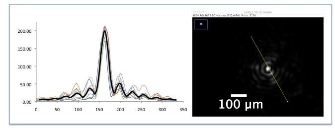
Then using the same technique, we compiled an intensity profile of the
Bessel beam at a distance z=340 mm behind the final lens. As expected,
the central spot size varies slightly in size and intensity over the axis
of propagation. We averaged the intensity of 10 different radial lines
that stretched the full diameter of the beam (which consisted of about 6
concentric rings). The central spot size at this distance was 44.4
microns.
Conclusion
The next steps would be to create a theoretical model of the Bessel beam’s intensity profile and then fit this model to the average intensity of the beam at a certain distance. Also, it would be beneficial to graph the z-dependence of the theoretical and experimentally determined central spot size.
Overall this research project proved to be a good pedagogic endeavor for a teaching lab, since it incorporated important broader topics in optics, such as diffraction theory and Fourier optics.
References
[1] Jeremy Kowalczyk, Stefanie N. Smith, and Eric B. Szarmes, "Generation
of Bessel beams using a 4-f spatial filtering system," Am. J. Phys.
{77} 229-236 (2009).
[2] Joseph Katz, Emanuel Marom, Glenn Spitz, and Naim Konforti, USA Patent
No. 5,080,456 (14 January 1992).
[3] J. Durnin, J. H. Eberly, and J. J. Miceli, "Diffraction Free Beams,"
Phys. Rev. Lett. {58} 1499-1501 (1987).