Advisors: Prof. Hal Metcalf / Dr. John Noe
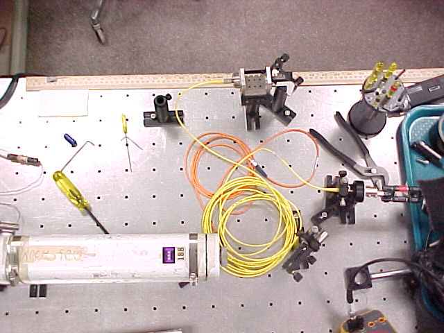
Apparatus description:
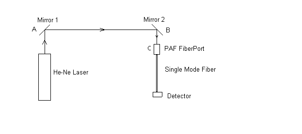
AB is approximately 30 cm. BC is approximately 5 cm. Mirror 1 allows for x-y alignment with only small tilt, mirror 2 allows for tilting the beam without much displacement. So the x-y and angle adjustments can be done separately.
      * Catalog Number: PAF-X-5-633
      * Effective Focal Length: 4.6mm,
      * (Coupling) Input Beam Diameter: 0.8-1.4mm,
      * Collimated Output Beam Diameter: 1.0mm,
      * Best Collimation Distance at 10cm & beyond.
        (for more information, see OFR)
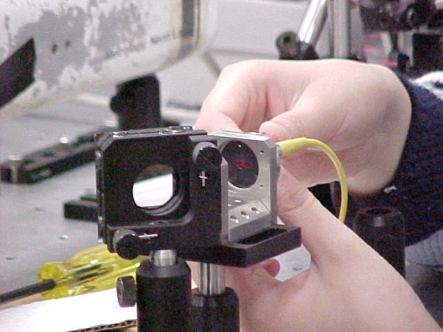
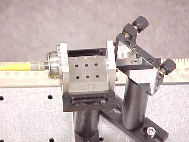
The Fiber Port (PAF) efficiently couples a collimated laser beam into a single-mode fiber or a multi-mode fiber. The position of the focusing lens has 5 degrees of freedom, x, y, z position and j, q angles.
       * Catalog Number: P1-3224-FC-5 (arrived in March, 2001)
       * Operating wavelength: 630 mm
       * MFD/Clad: 4.0/125mm
       * Length of the fiber: 5m
       * NA: 0.13
Other fibers used (not very good, you can see some light leaking at one end of them):
       1) FCS-633-2-FC/APC/APC (APC: end of fiber is angle-polished
          to minimize back-reflection loss) labeled as new, arrived
          at Feb 2000.

       2) FCS-633-2-FC/APC/APC labeled as old, 2m long.

       3) Labeled as SIECER optical cable 02/94.
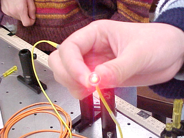
The output of the laser beam out of the fiber is observed with a photo detector (Thorlabs DET-110) together with a multimeter. It is important to choose the right resister for the photodetector: we need the load resistor as large as possible to get a good signal. At the same time, the voltage cannot be very high due the saturation of the photodetector. If we make the highest voltage 5 volts, the resister would be about 10 kohms.
'Focusing a collimated beam into a single-mode fiber is like searching for a golfball on a football field while blindfolded. It can be a difficult and time consuming repetitious process.' (from information about alignment procedure from OFR)
First adjust x-y screws on the side of the PAF in order to make the lens in the center of the Fiber Port by eye. Then center the laser beam on the input aperture of the PAF by two mirrors. Be sure that the laser beam is always paralleled to the horizontal plane.
Attach the fiber loosely to bulkhead and examine the output. If you see some light going through the fiber, try to maximize the coupling by two mirrors. Then move the fiber along the z-axis closer to the lens. After the fiber is fully attached to the port, adjust the three Z screws on the back of the port to change the z position. If lens is too far (close) away from the fiber, tighten (loosen) the z screws in Ľ turn increments.
Iteratively check the beam path and adjust two mirrors, and PAF z screws to maximize the coupling of the laser beam to the SMF.
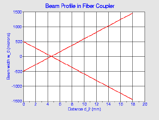
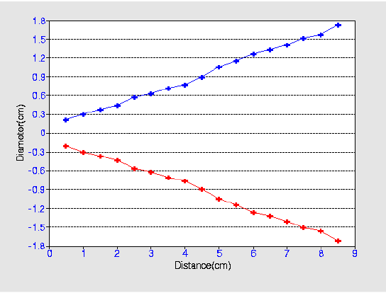
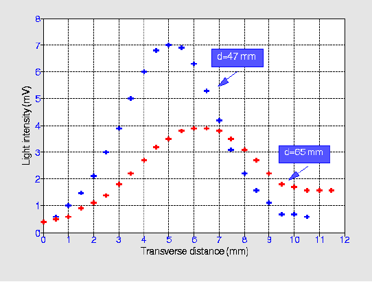
Slope (theoretical) = 0.10, the divergent angle is 12 degrees.
The graphs show the gaussian profiles of the laser beam coming out of the
fiber. For the blue line, L=47 mm, w=4.23 mm, NA=0.090. For the red line,
L=65 mm, w=6.10 mm, NA=0.094. ( L is the distance between the fiber end
and the photodector. They agree with the divergence of the input beam.
Note that intensity corresponding to w is determined by 1/e^2 of the
maximum intensity.
In order to see if the reflection light influence the stability of the
laser, we used a reflective glass to reflect the light back directly to the
laser to instable it. We observe the fluctuation with or w/o the glass, we found
that the outcome are almost the same. So I think for He-Neon Laser, the
effect of reflection light is not an important factor for the instability
of the output laser beam. Also, there is a small 2-3% fluctuation rom the
laser power supply. There would be some reasons.
The fluctuation of the intensity of the light out of the fiber is
an interesting characteristic to study more. As I mentioned earlier, the
light is leaking out of the other three fibers. The reasons about the
light losing are about to find. The other properties of the fiber, such as
polarization properties, are also interesting.
I am very appreciated for Dr. John Noe and for his instruction and
generous help, both for the physics and the webpage. I would like to thank
Prof. Harold Metcalf for ideas and help. Many thanks to Bob Azmoun for
helping me make the experimental set-ups and teaching me a lot
of things about the laser. Many thanks to Enju Lima for helping me
to finish the project.
1. Michael Hofmann, 'Experiments with Fibers', SUNY Stony Brook, 1999.
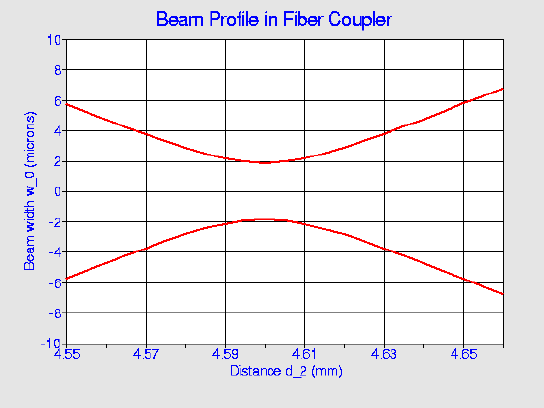
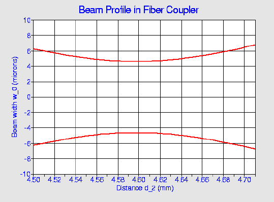
We can see from the graphs that if we use a lens after the mirror1 to
focus the light to a small spot, even if the fiber end reaches the focus
point, it just uses a small fraction of the total light. So the coupling
is not good in this case.
The fundamental mode field distribution of the single mode fiber can be
well approximated by a Gaussian function that can be written in the form
P(r)=Aexp(-r^2/w^2) ,
where w is referred to as the spot size of the mode field pattern. The
quantity d = 2w is usually referred to as the mode field
diameter (MFD).
      *  Laser beam: 3.727+/-0.027V,
      *  After Mirror 1: 3.19+/-0.084V,
      *  After Mirror 2: approximately 3V,
      *  After the Fiber end: 1.897=/-0.628V,
         Coupling about 63 +/- 20% of the light
         into the single mode fiber.

BUT, the intensity of the light fluctuates a lot. The higher the
intensity, the higher the fluctuation. There may be many factors, such as
the reflection light, the fluctuation of the environment, the mechanism of
the fiber, the unstable laser beam, etc.
5. Further Study
6. Acknowledgements
References:
2. Ajoy Ghatak, K. Thyagrajan: 'Introduction to Fiber Optics', Cambridge
University Press 1998.
3. Jeff Hecht, 'Understanding Fiber Optics', Published by Prentice-Hall,
Inc. 1999. Third Edition.
4. Frank L. Pedrotti, S.J. and Leno S. Pedrotti, Chapter 24 ,
'Introduction to Optics', Prentice Hall,1992
5. My Weblinks.
Back
To Home