Research Journal
Simons Program - Summer 2013
June - 24 | 25 | 26 | 27 | 28
July - 1 | 2 | 3 | 5 | 8 | 9 | 10 | 11 | 12 | 15 | 16 | 17 | 18 | 19 | 22 | 23 | 24 | 25 | 26 | 29 | 30 | 31
August - 1 | 2 | 5 | 6 | 7 | 8
Back to top]
video she made with pictures from throughout the summer.
Tuesday, 6 August 2013
Today was largely spent working on my poster, bringing together all of the images I have in a concise way. At four in the afternoon, we gave tours to the other Simons fellows. It definitely helped me figure out how I will speak on Friday. I also took a video of the laser light show, which I will try to upload and link here.
Monday, 5 August 2013
I spent the morning working on my abstract with Melia. In the afternoon, I finally switched the stress elements. The new one still has straitions, but they are much less noticeable. I adjusted the stress on this element until I was able to fit one of the alternating rings on the CCD camera. I will include these new pictures in my report
Friday, 2 August 2013
Today will be spent working on my report and cleaning up the lab. If I finish both of those, I will work on my poster. Otherwise, I will leave that and my abstract for the weekend.
Thanks to router problems, I was unable to connect to the shell to work on my journal, but the day was at least productive. I cleaned up my area, some of the equipment laying around, and some boxes. Dr. Noé helped Rachel put together the laser light show. I got to put on Dvorak, and some of the patterns it created were mesmerizing. I'll try to take a video later.
Thursday, 1 August 2013
I am still working on my report, but I feel as though my project is incomplete without quantifiable data. I think I will attempt to narrowly focus the beam and measure its beamwaist with and without the radial polarization, using this as a measure of the quality of the vector beam.
I realized that, unfortunately, there might be something wrong with my data or my analysis. When I passed circularly polarized light through the element, I still used a linear polarizer to analyze the polarization of the light. It is highly likely that the piece is therefore acting as another quarter-waveplate, but I will try putting a circular polarizing filter in the beam as soon as I can find another quarter-waveplate.
I remembered that I still have the pairs of 3D glasses from my presentation in June! Since 532 nm is in the middle of the visible spectrum, I was sure that they would suffice as a circular polarizing filter to separate left- and right-handed light, and it turned out to work almost perfectly. Since the beam initally propagates linearly polarized at a 45° angle, and I aligned the fast axis of the λ/4 waveplate horizontally, the beam is right-handed from the point of view of the source. This light passes through the left lens of the glasses and is blocked by the right lens. Knowing this, I placed each lens directly in front of the CCD camera, and took the following images. The image on the left was passed through the left lens, the image in the center was not passed through either lens, and the image on the right was passed through the right lens.
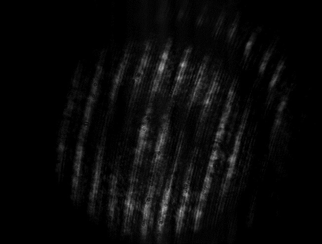
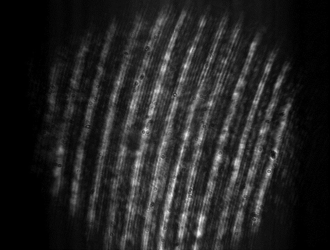
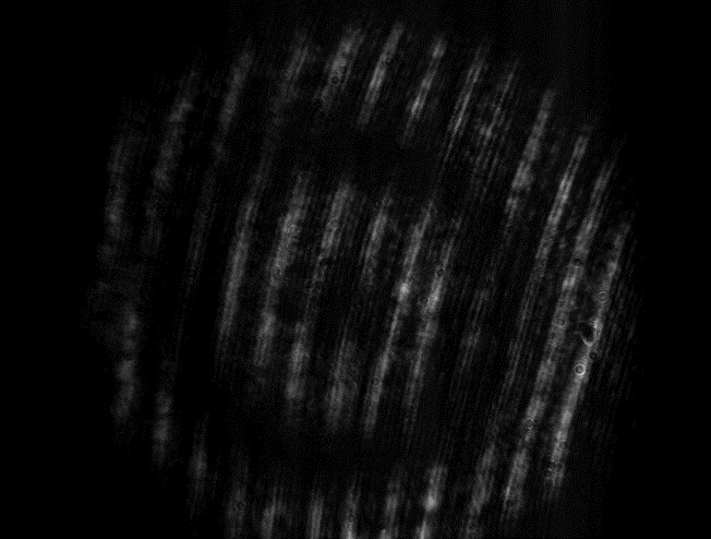
I think this makes it really clear how the birefringence in the element is varying with radius, and how the total beam is a composite of both left- and right-circularly polarized light. Since the laser output is polarized at a 45° angle and I aligned the fast axis of the λ/4 plate horizontally, the light is right-circularly polarized from the point of view of the source. Since the stress is balanced in the center of the element, there must not be any birefringence there, so the left lens must allow through circularly polarized light. I'm glad I thought of testing with the glasses; I was never able to find out which polarization passed through which lens online. I also read online that a λ/2 waveplate has been found to reverse the handedness of circularly polarized light, so this means that the bright rings are caused by retardance in even multiples of λ/2 on the left and odd multiples of λ/2 on the right. This also means that the edges of the bands should be linearly polarized, an interface between the left- and right-handed elliptically polarized light.
Wednesday, 31 July 2013
Unfortunately, the pictures I took yesterday are stuck on the old Windows 95 computer. Its CD drive is broken, and the lab does not have a floppy reader. With any luck, I will be able to transfer the pictures to my laptop for my poster and online report.
I am certain that I've produced cylindrical vector beams as described by Spilman and Brown. The quality of the beams is questionable, and appears to change with rotation. For instance, two lobes are clearly visible when the polarization axis of the rotational analyzer is aligned horizontally, but not vertically. This might be due to the striations, which also seem to be causing some glare. I tried to minimize this effect in the pictures.
For today's pizza lunch, Prof. Magnes and three of her undergraduate students at the Vassar Applied Optics Lab presented their work on biological applications of diffraction. Brian and Ramy talked about their preliminary work on diffraction to prepare a device that may study electric field fluctuations in Planaria that have been cut. I was very interested in Prof. Magnes' use of peer-reviewed video to publish her work online in an clearer way.
After Kathy and Rachel presented their work for its biological applications, I showed Prof. Magnes and her students my setup and explained the theory behind it. I spent the remainder of the day working on my online report, which I will add to my page by next week.
Tuesday, 30 July 2013
Today, I finished aligning my setup. At first, there was a very bright spot in the center of the beam. I tried to eliminate this by cleaning the lenses thoroughly. Afterwards, there was much less scattering from both the mirrors and the lenses, and I could clearly see a pattern of alternating rings of light and dark on the screen. These rings had centers in the middle of the image and towards the edges where the stress is applied. When I rotated the linear polarizing filter, the rings in the image appear to rotate in the opposite direction. When the polarizer is aligned with one axis, the image has a singularity in the center.
I was sufficiently satisfied with the image to set up a CCD in the beam to take pictures of the image. Unfortunately, the striations I observed earlier are much more apparent in the CCD, due to the small size of the diode. I tried to set the laser to a power which did not max out any of the pixels, but the outer rings became faint. I'll have to take combinations of pictures at different powers. I think a 45° difference will be enough to show the rings rotating, especially since the laser emits light polarized at a 45° angle with the vertical.
I finally got the pictures I wanted. By moving the collimating lens slightly closer to the laser, I was able to keep the light from focusing too narrowly. I passed both vertically and circularly polarized light through the element, and I used a linear analyzer at 45° intervals for each. For vertically polarized light, I also placed a half waveplate with its axis vertical and at a 45° angle. According to past research, this could produce both radially and azimuthally polarized light. I panicked when I saw that the rotation of the images went the wrong direction, but then I realized the camera produced an upside-down image.
The Simons talk today was given by Asst. Prof. Heather Lynch from the Ecology and Evolution Department. She discussed her research on Antarctic penguin populations and how she uniquely approaches the problem of penguin census-taking through mathematics and high-resolution satellite imaging.
Monday, 29 July 2013
This weekend, I read up on 4-f systems in order to understand the theory behind them. I also read through much of Melia's journal and REU presentation from last year to find out more about how they work and how I might be able to build one in the lab. I'll have to spend some time carefully cleaning one of the tables; the system requires more space than I currently have, but I want to avoid disturbing the laser that Sam Goldwasser was working on while he was here. Following Dr. Noé's advice, I also bought a can of Pringles this weekend. Not only are they crunchy and delicious, but the lid to the can has interesting birefringent properties. After passing circularly polarized light through it, it exhibits a very similar pattern to the stress optical element: a series of concentric rings. However, the rings formed by the lid are much more irregular than the circles formed by the stress element. They still both appear to rotate when the polarization axis of the analyzer is turned.
I spent some time this morning making my journal more accessible by adding a table of contents at the top with references to each daily entries for the duration of the Simons program. The bottom of each entry also now has a "Back to top" reference, to return to the table of contents.
The laser I'm currently working with is not well-collimated; rather, it diverges comparably quickly. One benefit of this laser's divergence is that I need less room for a beam expander. I will only need one lens to collimate the light before passing it through the element. I decided to measure the divergence to get a better idea of where to place the lens. I plotted my points in Excel, and I got a regression line of

Since the device I'm working with has a diameter of 1.3 cm, I'll use a lens with a focal length of 20 cm.
With Melia's assistance, I cleared off a section of table to create a 4-f system using the 333 mm lenses Melia used last year.
Friday, 26 July 2013
This morning, we went over another estimation problem with Melia:
What would the mode spacing of a HeNe with a cavity the length of Long Island be, and how many different modes would the laser have?
From living on the island, I knew that it is about 50 miles from my house to Manhattan, and approximately 70 miles from my house to Montauk. I figured 200 km is a good enough estimation. (Although the island is actually only 190 km east-to-west, a straight line from New York Harbor to Montauk Point would run east-northeast, so this is a fair estimate.) The following equation gives the difference in frequency between adjacent modes of a laser:

That allows us to calculate that adjacent modes in the Long Island Laser would be 800 Hz apart. Given that the typical gain bandwidth of a red HeNe laser is 1.5 GHz, this laser would have approximately 2x10⁶ modes. I thought this laser might mode-lock in an interesting way, but it turns out that the bandwidth is the actual limiting factor for the minimum duration of the pulse.
After going over the estimation problem, I decided to make lemonade out of lemons and look at the mathematics behind polarization. I remembered Jacob's journal and report describing something called Stokes parameters, which quantified the polarization of a beam. It turns out there are other ways of quantifying polarization as well, each of which has its own benefits. Jones calculus utilizes complex vectors to describe light in terms of the amplitude and phase of its electric field. Transformations on these polarization vectors, such as those done by polarizers, can be described by Jones matrices, which operate on the vectors.
There were numerous optical elements on the table that were not labled, so I tested them in the polarized beam to see what they were. It turned out that one was a λ/2 plate and another was a λ/4 plate for the 532 nm laser I am using. The others did not exhibit characteristics of quarter- or half-waveplates, so I figured that they must be for another wavelength, probably 635 nm. I still have to clean up the image, which I will probably accomplish with a 4-f system. By the end of the day, I had the following setup:
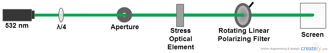
The stress optical element I'm using is from Jacob's project. It is a cylindrical piece of plexiglass to which pressure can be applied radially at three evenly-spaced angles. The image produced is similar to what I observed yesterday, but with the quarter-waveplate creating circularly polarized light, the image has a series of alternating rings in the center.
Thursday, 25 July 2013
This morning, I set up a page of links, accessible through my main page, with papers about cylindrical vector beams. I looked into setups I can make using the stress optical element Giovanni brought yesterday. I then spent several hours putting together the setup and aligning the elements, but the waveplates are designed for green light at 532 nm, and the laser I was using produced 632 nm. I moved the elements to the other laser and realigned them. The green laser diverges very quickly, so I had to use a collimating lens.
It turns out that the device is really deformed. Unlike the bands that Jacob observed, the light only formed a triangle on the screen. This was probably due to surface deformations on the element, as the image is highly striated.
Wednesday, 24 July 2013
Today, Giovanni visited the LTC and attended our pizza lunch meeting. Giovanni, a former undergraduate in the LTC, is currently a doctoral candidate at City College of New York. He brought back a stress optical element in which the stress is applied symmetrically with m=3. At meeting, he gave a talk about "Encoding Information with Vector Vortex Beams." He described how vector beams with angular orbital momenta of higher order than the zero-order Gaussian beam can be used to efficiently transmit up to four times the amount of information within a single fiber. He then drew conceptual analogies between the representation of these beams as the sum or difference of circularly polarized light and quantum entanglement in Bell states.
After Giovanni's talk, we went to the Ultracold Lab, where Jeremy, a PhD student in the lab, gave us a tour. He explained their work creating and observing ultracold rubidium crystals. At the end of the day, Dr. Noé kindly took some of us out to dinner. We ate at Luigi's with Melia, Giovanni, Stefan, and Prof. Metcalf. At one point, the topic strayed to my college plans, and Prof. Metcalf made clear that I should foster good relationships with a few professors in college, and not merely attend my classes.
Tuesday, 23 July 2013
Today, I spent most of my time researching cylindrical vector beams. These are beams with axial symmetry, and can either be polarized radially or azimuthally. Both cylindrical polarizations result in a singularity in the center of the beam, due to a phase discontinuity. Cylindrical vector beams have numerous interesting properties. For instance, radially polarized beams, when focused, have significant longitudinal polarization, and can be focused much tighter than linearly polarized beams. Holography using a spatial light modulator is a very effective means of creating cylindrical vector beams, so I will hopefully be able to use the SLM that the lab recently acquired to create these beams.
Monday, 22 July 2013
This morning, we went over Melia's estimation problem:
If we covered all of the roofs of buildings on Stony Brook's camous with solar panels, how much energy could we produce in 12 hours?
I supposed that there were apporximately .5 km2 of buildings to place solar panels throughout the campus, including the hospital and health sciences. I found online that the intensity of direct sunlight is approximately 1 kW/m2, and solar panels can convert this into electrical energy with an efficiency of about 15%. Over the course of 12 hours, this gives

I found that a large skyscraper in Midtown Manhattan can use 1000 kWh per day, so the electricity from the Stony Brook Solar Array could power 900 skyscrapers.
Friday, 19 July 2013
Today was the Simons trip to Brookhaven National Laboratories. Throughout the day, we toured different sites at BNL. Unfortunately, the bus had no AC to protect us from the humid, 93°F weather. First, we were taken to the Office of Educational Programs, where Scott Bronson met us, talked briefly about the lab, and showed us an outdated promotional video. We were then bussed to PHENIX, where we got to see the detector and we learned about the research teams who analyze the data. We then ate went to the computer systems building, where we saw New York Blue and BlueGene, computers with huge amounts of processing power (upwards of 100 teraflops). The two supercomputers were excellent examples of Moore's law, since New York Blue has 103.22 teraflops from 18 racks, which can be accomplished by only 3 racks of the new BlueGene.
After lunch, we were given a presentation on the new Long Island Solar Farm at BNL. We were told of all the benefits this array can have for the future of solar energy in the Northeast. After a discussion of the differences between private, public, and university laboratories, we went to the National Synchrotron Light Source. During our brief tour, we were told of a few of the projects being done at the NSLS, soon to be replaced with the much more advanced NSLS II.
Thursday, 18 July 2013
I think I'd like to do my Simons project on stress birefringence, so I spent this morning looking at Jacob's journal and project. His apparatus is no longer at the LTC, but he left explicit designs, which are sufficiently reproducible. However, his apparatus was designed solely to test compressive stress in plexiglass, and I think I would like to test a different material, such as polyethylene, or tensile stress instead.
Wednesday, 17 July 2013
Today, I had to work on a presentation of my progress doing literature research, which I will be presenting during our weekly pizza lunch. I included my research of solar concentration and stress-induced birefringence. Just before lunch, we went outside and took the annual LTC picture.
During the meeting, Laser Sam gave an interesting presentation on the history of lasers, the different kinds of lasers, and how they work. He also talked about Fabry-Pérot inferometers. I found it so interesting that the material has such a high internal reflectivity that the speed of light acts as a limit to the speed at which the device operates. I learned from Casey's talk that energy sublevels are actually a result of magnetic flux passing through an atom.
Tuesday, 16 July 2013
Today, I shifted my focus away from solar concentrators and nonimaging optics, instead looking at photoelasticity and induced birefringence. Essentially, the index of refraction of certain materials can be affected by a stress, such as plastics or glass. This can have a polarizing effect on light that passes through the material.
I thought this might be related to the whitening of certain plastics caused by tensile forces. However, it turns out that this is due to a process called crazing. In polymers, Vaan der Waals forces can be overcome by the application of stress, causing microscopic gaps, which are visible because light reflects differently off of them. I might want to analyze the change in reflected spectra of a plastic as it undergoes crazing.
Monday, 15 July 2013
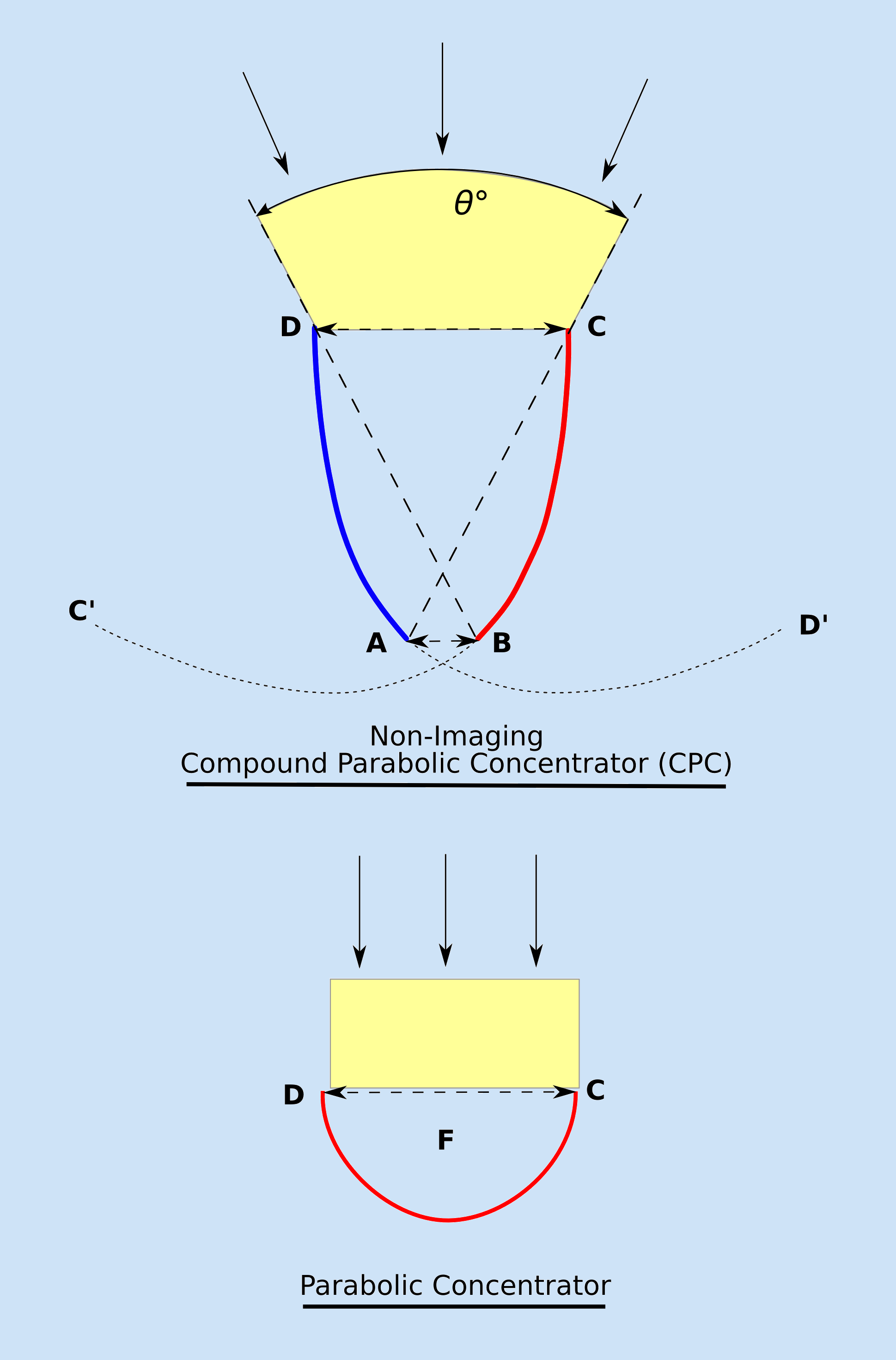
Today was "Laser Sam's" first day at the LTC this summer. Before he came, I did more research on nonimaging optics on the Optics Infobase. I read about Compound Parabolic Concentrators, an efficient nonimaging device which has a theoretical maximum concentrating power of 1/sin2θ, where θ is half of the angle of acceptance for the larger aperture. The diagram below demonstrates the angular advantage of CPC's over simple parabolic reflectors.
In other news, I finally understand etendue in a mathematical way:
G represents the total etendue of a system with a luminous surface Σ and an irradiated surface S for which F is the view factor from Σ to S, or the proportion of light from Σ that reaches S. It is assumed that the medium between the surfaces has a refractive index of 1.
My understanding was aided by learning more about solid angles (Ω) and how they differ from one-dimensional angles.
Friday, 12 July 2013
This morning, Melia went over an estimation problem regarding the angular resolution of the eye. I solved this using a single black pixel on an otherwise white screen on my laptop. I could first see the square pixel from a little more than 2m away, and my laptop screen, which is 20cm high, consists of 1080 horizontal bars. The others did this using a formula that regards the eye as an aperture and calculates diffraction. My calculated value was actually the smallest one, but that might have been due to my glasses.
Later in the morning, we went to the conference room. Samantha showed us some basic functions of Python, which she encouraged we use for data analysis and plotting. She suggested that we download Ubuntu to use a more sophisticated version of Python. We then spent the next hour navigating the American Journal of Physics website, using keywords to find interesting articles relevant to each of our topics. Finding very little relating to nonimaging optics, we then went to the Optical Society of America's website, where we found much more.
I spent the afternoon researching Linux distributions. I wanted to see which one would be the best for my work, since I need to balance capability and ease of use. Despite what I expect to do with Linux, I am not yet knowledgeable enough to use a potentially more powerful but less user-friendly distribution. I think Ubuntu will serve my purpose as a good introduction to Linux-based operating systems.
Thursday, 11 July 2013
I continued reading the books Dr. Noé lent me yesterday. I encountered some multivariate calculus, for which I am trying to find a resource. Melia also sent me a link to a thesis on maximum power point tracking (MPPT) algorithms for use in solar cells. This brought my attention to another article which went a little more in depth regarding the device as opposed to the general tracking algorithms.
Wednesday, 10 July 2013
I began the day by reading about étendue, a measure of how light diffuses in both area and angle. This can become problematic when dealing with solar cells because the overall étendue of a system can never decrease.
Today was also Samantha's first day in the lab. At our weekly pizza lunch, she gave a presentation on her work veriifying the classification of blue stars from the Sloan Digital Sky Survey by analyzing their spectra. Astoundingly, she found that about 10% of the stars studied had been misclassified by the device's automated template matching system. She also talked about how she first got involved in science research, including her involvement at Rensselaer Polytechnic Institute and her participation in high school fairs like Intel STS.
After Samantha's presentation, we stayed in the conference room and had an LTC meeting. Everyone shared their ideas and progress. Dr. Noé mentioned that light can also be polarized longitudinally. When I shared my plans, he encouraged me to look into something with more mathematical leaning in the topics I am currently pursuing. He suggested looking at optical beats, perhaps using an oscilloscope to produce sound from these beats. At the end of the day, he lent me two books, one on sonoluminescence and one of Fourier series.
Tuesday, 9 July 2013
This morning, Melia discussed the second estimation assignment with us:
What focal lengths are needed for a beam expander with the magnifying power to fill an aperture the size of the umbilic torus?
How far from the aperture could the far-field diffraction pattern be observed?
The first problem only required an estimate of the diameter of the aperture and the equation for magnification of a beam. I assumed that the beam would start out about 1mm in diameter and estimated the central hole of the umbilic torus to be about 5m in diameter. Magnification is described by the following equation:

Since this is also the ratio of beam widths, I would use lenses with focal lengths of 1mm and 5m.
The second part required more mathematics. The far field is defined by the following relation:

in which W is the diameter of the aperture, λ is the wavelength of the light, and L is the distance from the aperture. Solving for this distance gives

Using 5m for the diameter as before and 650nm as the wavelength of red light, I found that the far-field diffraction pattern could appears much more than 40,000 km away.
I also wrote my first entry in my lab notebook with my notes from the project yesterday. This was quite daunting at first, but with the aid of a ruler, I was somewhat satisfied with my illustrations. I will have to print out my more detailed diagrams at home, since I do not have the drivers for the printer here. I was surprised to find that the photodiode we used as a detector yesterday is very similar to typical solar cells. In fact, solar panels usually consist of large photodiodes in photovoltaic mode.
In the early afternoon, I attended a talk by Dr. Jessica Seeliger of the Department of Pharmacological Sciences. She discussed her research on the chemical biology of pathogens, namely M. tuberculosis. After discussing her work, she described the "Semi-Random" path she took on the way to her current area of study. She also allowed us to ask questions about her career in science research.
At the end of the day, I spoke to Dr. Noé about my ideas. He thought that sonoluminescence might not be very applicable or current. He was receptive to my idea to study CLFR's, and he showed me a recent article about solar tracking. He also encouraged that I continue looking into other topics, especially my interest in acoustics.
Monday, 8 July 2013
Today, I read more articles about CLRF arrays. This seems to be a much better method for concentrating light than lenses, provided that reflectors are sufficiently reflective. However, it seems that reflectivity would be a smaller obstacle to overcome for maximum efficiency.
In the afternoon, Melia gave us a mini project to make a beam expander and measure the beam created. Below is a simplified diagram of the Keplerian beam expander that we constructed.
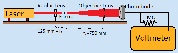
The occular lens we used had a focus length of 125mm, and the objective lens had a focus length of 750mm, giving our expander a magnifying power of 6. This was obtained by the following:
We put the photodiode with a 200 μm pinhole on an adjustable mount to measure the intensity of the beam at different points along it. The 1 MΩ resistor was placed in parallel with the voltmeter (which is not evident in the diagram). This would maximize the current passing through the device. Kevin used MatLab to plot our data and calculate a best-fit Gaussian curve. A position of 0mm was given to the peak, and intensity was scaled relative to the peak as well.
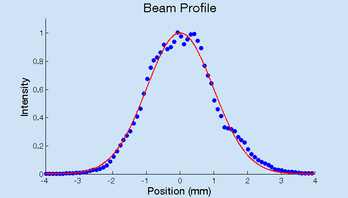
The data we collected plotted nicely onto a Gaussian curve. However, there were some anomalies caused by the nature of our setup. The adjustable mount was not entirely steady. Since measurements were taken every 100 microns, a small jolt could have set back the photodiode or pushed it forward.
Friday, 5 July 2013
In the morning, we went over our estimations for the question, "How much rubber is worn off all tires in the US in one year?" I slightly overestimated, but I was only off by a little more than one order of magnitude. Melia gave us two new problems involving beam expansion and far-field diffraction, using the umbilic torus as an aperture.
I looked more into the use of Fresnel lenses as solar concentrators. I found a good article that describes a number of their uses. It turns out that they differ very little from traditional lenses except in size. Their use is generally considered for cost-effectiveness, especially since they can easily be made of a clear plastic, such as crylic. Below is a diagram of a conventional lens and a Fresnel lens focusing collimated light.
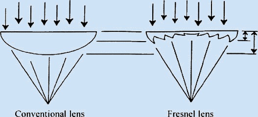
There is some light loss due to refraction on the sharp angles, and the Fresnel lens causes significant aberration, which sometimes requires another concentrator. Loss can be anywhere from 20% with a large focal distance to 80% with a short focal distance. However, this is still much better than many typcial cells, since it allows for a smaller cell component to capture the same amount of sunlight. I also found that many current solar arrays use Compact Linear Fresnel Reflector (CLRF) fields to send sunlight to a central tower. This is more efficient on a large scale due to the need for only a few receivers in a huge array of mirrors. Since these mirrors are generally detached, they can also pivot to catch sunlight optimally. I have seen these gigantic solar farms before, but I never realized that the concept behind them is the same as Fresnel lenses.
Wednesday, 3 July 2013
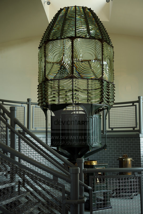
Last night, I remembered a past trip I took to the Fire Island lighthouse where I saw the original Fresnel lens in an adjacent building. This morning, I began to research the possible things I could do involving these lenses. One application I found was as concentrators for solar cells. Since image clarity is not a concern for solar cells, Fresnel lenses are an ideal method for focusing light onto a smaller area.
In the afternoon, Dr. Cohen came to the lab. Rachel and Melia showed us some patterns they had made with circular, triangular, and square apertures. The circular aperture formed an Airy pattern, but the other two were more interesting. The square aperture formed a square with a series of dimmer rectangular bars on each side, and the triangular aperture formed a series of bars that reminded me of a deltoid curve.
Tuesday, 2 July 2013
This morning, Melia talked to us briefly about estimation problems. She explained that sometimes, the order of magnitude is the most important part of a problem, and being able to estimate well can aid with preliminary calculations. We worked through one of these problems together:
"How tall is a stack of one trillion one-dollar bills?"
Using an estimation of the thickness of a large book, we calculated that the stack would be approximately 2*108 meters tall. The accepted value (source) for this is 108 m, so our estimation was close. Using an estimate of the width of the United States, we then calculated the circumference of the Earth, finding that this stack would circle the equator multiple times. (Our calculations ended up overestimating this number, but we were still within one order of magnitude.)
I spent the rest of the morning researching inharmonicity on both the piano and various string instruments. I found several similar articles regarding human perception of inharmonicity of digitally synthesized tones. I found that in piano, the differences in inharmonicity result from an excess of tension or mass distribution that causes the string to deviate from the ideal. In an ideal string, the partials have frequencies that are integer ratios of the fundamental. More generally, if f0 is the frequency of the fundamental, then the frequency of the n-th partial, or fn, is described as

For a real string, this becomes
where B, the inharmonicity coefficient, is described by the following equation:
in which Q is Young's modulus, d is the diameter, T is the tension, and l is the length. Importantly, even the first partial is slightly inharmonic, despite this partial usually being considered as the fundamental. In truth, the first partial has the least discrepancy from its ideal frequency.
I hope to find more on the differences in inharmonicity between stringed instruments. Most studies focused solely on the piano or on a synthesizer, and even more regarded only differences in human perception of specific inharmonicities.
In the early afternoon, we went to the Wang Center for a talk by Professor Carlos Simmerling about what it is like to perform research and the benefits of researching between traditional branches of science. He emphasized the importance of creativity and open-mindedness in research. Above all, he encouraged us to pursue questions that inrtrigue us, so that we are always excited by our research and the promise of discovering something unique. He also proposed finding our own unique interests throughout college in order to offer a broader range of abilities to a potential employer, including the ability to communicate our research to others in the scientific community, journals, and foundations for grants.
Monday, 1 July 2013
Today, I read more about sonoluminescence and some of the processes that create it. I found an article that describes an inexpensive apparatus to create and observe single-bubble sonoluminescence. I included their diagram below.
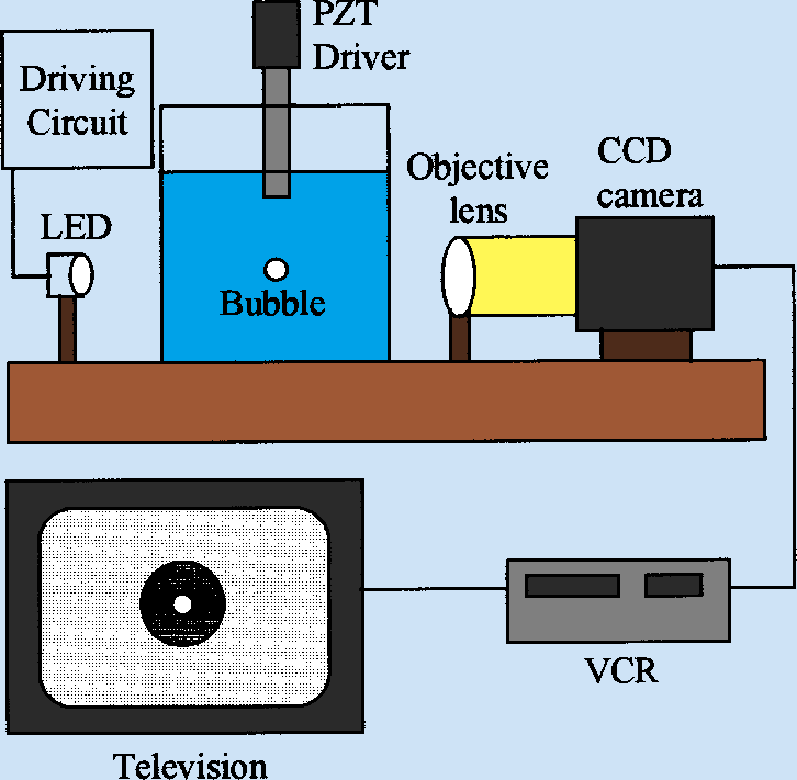
The system contains a piezoelectric transducer (ie. a speaker) that traps the bubble stationary and that creates the effect by providing a steady oscillation. The LED allows the bubble to be observed at different points in its oscillating cycle. The VCR could now be replaced with a higher-resolution and higher framerate recording device for better playback and analysis.
I also found an article which addressed sonoluminsecence in the presence of dissolved gases. It stated that there is a concentration of a dissolved gas that results in maximum cavitation, and that cavitation is decreased with both an excess of dissolved gas and no dissolved gas.
Friday, 28 June 2013
Today, Dr. Noé gave a lesson on the nature of waves as described by complex numbers. He taught us that infinite plane waves can be described by the equation
and that spherical waves can be described by the equation
where ![]() is referred to as the wave number. We then talked about how the equation for spherical waves can be used to solve the double-slit problem. Since the distance to the screen (L) is much more than the distance from each slit to the point halfway between them (a), a number of variables create insignificant error. This includes the change in time and the decrease in intensity with distance. Additionally, this means that their ratio,
is referred to as the wave number. We then talked about how the equation for spherical waves can be used to solve the double-slit problem. Since the distance to the screen (L) is much more than the distance from each slit to the point halfway between them (a), a number of variables create insignificant error. This includes the change in time and the decrease in intensity with distance. Additionally, this means that their ratio, ![]() , is sufficiently small to use the first order approximation to the binomial theorem,
, is sufficiently small to use the first order approximation to the binomial theorem, ![]() . Since we are also dealing with small θ, the small-angle approximation,
. Since we are also dealing with small θ, the small-angle approximation, ![]() , is also sufficient. This can be drawn as follows:
, is also sufficient. This can be drawn as follows:
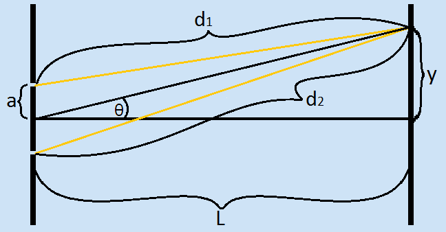
We used the Pythagorean theorem to find d1 and d2. Utilizing the fact that intensity is the product of amplitude and its complex conjugate, we found that the intensity of the pattern varies by the following approximation:
where k is the wave number as before, and a and θ are as shown in the diagram. We also learned that most visible light lasers have an angle of divergence of about one milliradian.
Melia and Rachel also showed us how to use LaTeX. I spent some time in the early afternoon familiarizing myself with a LaTeX equation editor, which I have used to create the equations in today's journal entry. I also began working on an "Ideas" page, for which I am currently researching topics.
Thursday, 27 June 2013
This morning, I looked at past projects from the LTC for inspiration. I liked the part of Angela's report that addressed the differences in inharmonicities between the low and high registers of her piano, but I was upset to note that she only studied one piano. My piano teacher told me a while ago that there is significant difference between overtones of grand and upright pianos, due to the varying length and tension of the strings. If I were to study this, I would analyze differences in inharmonicity between strings for the same note on different pianos to see if the type of piano actually makes a significant difference. I also would want to test the difference between strings on the cello and violin, and see how they compare.
At noon, we were required to attend a Lab Safety lecture. The talk had little to do with the research I forsee myself doing at the LTC. Instead, it focused on the proper handling and disposal of hazardous materials.
After the lecture, I returned to the lab and continued to look at old projects. I really enjoyed reading about Ken's project on sonoluminescence. Although his work was performed more than ten years ago, it remains relevant with the discovery that mantis shrimp give off sonoluminescence from cavitation bubbles created when they strike with their claws.
I also read more about Moiré Patterns, discovering that I had noticed a certain kind of them long before realizing what it was. In tenth grade, the front cover of my agenda had a design of concentric circles, alternating between transparent and opaque. The page directly beneath had a similar pattern, but of alternating bars instead. When given nothing else to do, I would often shift the cover relative to the inside page and admire the patterns. I want to look more into these, since it seems as though certain kinds might be able to simulate interference patterns of waves.
Wednesday, 26 June 2013
This morning, I continued work on my talk on the use of polarized light for 3D. After finishing, we met in the conference room with professors, graduate students, and other Simons fellows from the physics department to have lunch and present our talks. I was very interested in Rachel's discussion of Elastic Light Scattering by bacterial colonies, and I plan on looking further into that. I was most intrigued by the use of the travelling salesman problem in minimizing scanning time. My presentation went much better than I had expected. In spite of my fear that I would lack material for a ten-minute talk, I was able to fill the time. I still need to work on my logical progression of thought during my presentation and the distribution of time to allot each aspect of my presentation.
After lunch, we immediately went to the Honors College Lounge in the Melville Library for a lecture on the Responsible Conduct of Research. The presenter discussed the necessity of ethical practices in performing scientific research, as well as the online CITI modules we will have to take. We took pictures for the Simons program by the Umbilic Torus.
Tuesday, 25 June 2013
Today, Dr. Noé reviewed the difference between the terms diffraction and interference. He explained that diffraction was a result of the Huygens Principle, which states that waves propogate as if each point particle on the wave front is a source of new waves. He explained the difference between intensity and amplitude, and how mathematically, the amplitude can be described as a vector or a complex number. We will go over the intricacies of this model at another time.
For the rest of the morning, I continued preparing a presentation and notes for my informal talk tomorrow, Creating 3D Effects for TV and Film Using Polarized Light. I investigated several additional methods used for stereoscopy, including anaglyphsandactive shutter glasses.
In the afternoon, I continued gathering information for my talk. I came across an interesting fact about the circular polarization of light. To polarize light this way, it must first be polarized linearly at a 45° angle. The beam must then be passed through a quarter wave plate (QWP) made of a birefringent material, which gives the light its circular polarization. To absorb circularly polarized light of a specific handedness, it must be passed through another QWP and then a linear polarizer. I found it interesting that the handedness (and even eccentricity when dealing with elliptically polarized light) is determined by the angle made by the axis of the linear polarizer and the fast and slow axes of the QWP.
Monday, 24 June 2013
Today, I started the Simons Program at the Laser Teaching Center. There was a brief reception in the SAC, and then we met with Dr. Noé and went down to the lab with our families and the undergraduates working in the lab this summer. He showed a number of tools available to us at the LTC, including different polarizing filters. With the filters, he demonstrated the differences in polarization with liquids and solids. While the light transmitted through the solid film changed color when the film was rotated, the color of the light transmitted through the liquid was determined entirely by the placement of the filters. He told us that this was because the molecules in a solid are fixed relative to each other, and the molecules in a liquid are not. He showed us the pattern formed when a split beam of laser light is allowed to interfere with itself.
We discussed focal length of lenses and the different kinds of images they produce. We then went outside to demonstrate how powerful a focused beam can be. Using only magnifying lenses, we focused light from the sun onto black pieces of paper. The beam was so intense that the paper was burned through, and nearly lit on fire. Dr. Noé also brought out a pinhole camera, and we discussed the properties of the image it produced. The image grew larger and more circular as the sheet of paper we used to observe it was placed further from the pinhole. Despite the change in distance from the pinhole, the image remained focused. We surmised that this is due to the divergence of rays from the pinhole.
In the afternoon, we brainstormed titles for our talks on Wednesday, and discussed the nature of these talks. Dr. Noé stressed the importance of trial-and-error in choosing a proper title. He also reviewed with us some of the practices of the lab, such as the research journal and the importance of keeping a neat and aesthetic research notebook. Rachel showed us her guide to Linux-based directories and HTML.