December, 2006
I submitted a paper to Intel STS that essentially discussed the properties of the liquid lens in the context of focal length variability in general as well as the functioning of the lens as a simple microscope. Most of what I've done is covered in the Liquid Lens page, previously the Miniproject page referred to below.
Monday, August 21, 2006
Refer to Miniproject Page for microscope stuff.
Tuesday, August 1, 2006
The arrival of the computer cable today was extremely helpful. I cleaned up the computer cart and cleared a workspace on one of the optics tables, where I first put together a simple microscope to image with the camera, and then spent some time trying to do the same thing with a water droplet instead of a glass lens. One issue with the small drops of water is that their focal lengths are extremely short, and the CCD sensor of the camera is relatively deep into the casing of the camera, making it hard to get the droplet physically close enough to the CCD.
Monday, July 31, 2006
Following up on the electrowetting lens: I've been playing around with
the idea of deformable lenses. By placing a drop of water in the opening
of an adjustable apeture, the diameter of the water drop can be adjusted
while the volume stays (pretty much) the same, which alters the curvature
and shape of the drop, resulting in a change in focal length. The smaller
the diameter, the more curved the surface of the drop becomes, which
shortens the focal length.
Thursday, July 27, 2006
Reading about the Shack-Hartmann's use of a lens array and Dr Noé's comparison of the effect of water drops in a screen producing multiple images has brought me through a whole bunch of topics. On the water note, one current technology that is being pursued is the usage of liquids (water/oil) to create extremely small lenses (used in cell phone cameras and some medical equipment) that can be adjusted to autofocus images. The lens is formed from the interface between a conductive liquid (water) and a nonconductive liquid with equal densities but different indices of refraction. This allows the lens to be oriented in any direction without being deformed or displaced due to gravity. The shape of the lens is altered by changing the voltage across electrodes in the lens container. The conductive fluid is manipulated according to the electrowetting effect, which manipulates droplets of conductive liquids with an electric field.
Lens arrays are also used for intergral imaging, which uses a microlens array to translate an image into an array of "element images". ...
Tuesday, July 25, 2006
In order to measure the radius of curvature of the convex mirror, Dr Noé and I went to the shop to use a little spring loaded dial gauge capable of measuring heights to the thousandth of an inch. Sometimes relatively simple mechanisms can be really impressive. I used the measurements to calculate the radius of curvature, and now have basically all the information necessary to model the mirror system.
I spent some time with Dr Noé looking up assorted topics in the field of Optical Fabrication and Testing. We came across many interesting "hot topics" that are relevant to an extremely diverse range of fields.
Shack-Hartmann wavefront sensor: The Shack-Hartmann sensor is used to detect aberrations (caused by atmospheric conditions in the case of telescopes, or in the eye when applied to optometry) and is often used for adaptive optics. It is based on (developed by Shack) the Hartmann test, which is a method of testing for aberrations in telescope mirrors that places a large, opaque panel containing a grid of holes in front of the mirror's surface. This effectively reduces the incoming light to a grid of points. The array of points passes through the mirror/telescope and is imaged before and after the focus. The deviation of points from their initial place in the array yields information about aberrations in the mirrors.
The Shack-Hartmann sensor replaces the panel of the Hartmann test with an array of lenses. In adaptive optics, light that has been collected by the telescope is collimated and divided by a beam splitter. The deflected beam is passed through the lens array, which reduces the beam to an array of points. The deviation of each point from its spot on the lens array is used to calculate the tilt of the wavefront, which is then used to correct the image produced by the other portion of the beam.
Monday, July 24, 2006
I've been looking at various Optical Testing techniques, and the seemingly endless array of interferometric tests is a bit overwhelming. The tests themselves are interesting and can be quite complex. In spite of (maybe because of) the breadth of the field, it's still difficult to go from seeing what others have done to coming up with something for myself.
I'm particularly interested in tests using gratings to create a moire interference pattern. One cool example is shadow moire, in which only one grating is used, and it is placed in front of the subject. A light source is used to create a shadow of the grating on the surface of the subject. When viewed off-axis but still through the grating, a moire pattern forms between the shadow of the grating and the grating itself.
The usage of moire fringes in making contour maps is extremely interesting, and in principle is very similar to tests of optical surfaces, since contouring determines the deviation of a surface from a plane, and optical surface tests measure the surface patterns of mirrors/lenses. The actual translation of fringe patterns to three dimensional coordinates, however, seems to be pretty involved mathematically.
Friday, July 22, 2006
I've been working on a pig-mirror telescope incorporating the concave
mirror with the hole in it (from the top of the toy) and a aide view
mirror accessory that lets you see cars in the blind spot (a small convex
mirror). The basic objective is to set up a Cassegrain style reflecting
telescope, but before doing so I need to calculate the focal length of the
convex mirror. I put together a setup with a micrometer and a elevated
rectangle of plexiglass so that I can take measurements of a laser beam
being displaced in relation to the displacement of the mirror itself. At
the focal length of the mirror, the displacement of the point on the
screen should be equal to the displacement of the mirror. This is easier
to picture with the example of a vertical laser sweeping across a concave
mirror. The point created on a screen one focal distance away will never
move, since the laser will always be reflected to the focal point. If the
mirror is moved instead of the laser, the focal point of the mirror will
be moved accordingly, which would be shown by the movement of the laser on
the screen. The same holds true for a convex mirror.
By comparing the displacements of the mirror and the image of the screen,
it is possible to calculate the focal distance of the mirror. Here's a
crude animation of the test:
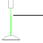
After calculating the focal distance, I'll use the data to model the telescope with matrices and predict the image distance. Mike was really helpful in explaining matrices and how they're used to show the propagation of light through optical systems.
Tuesday, July 18, 2006
I took a look at a study that used Moire interferometry as a means of measuring displacement in and out of a plane. The study incorporated a single polarized laser beam that was split by a polarized beam splitter. What's cool about this is the fact that the polarized beam splitter divides the beam into it's components based on the direct of polarity, so using a wave plate it's possible to change the direction of polarization of the beam and change how much of the beam is diverted by the beam splitter. One of the beams is passed through two glass wedges that alter the optical path length and phase-step the beam. The beams are directed into optical fibers and are reflected symmetrically onto the sample, which has a grating on it. The light reflects off of the sample and the interference pattern is viewable. The interference pattern varies in intensity based on the displacement of the sample in and out of the plane.
I decided that studies like this, with immediate and obvious practical applications, are what interest me. Dr Noé suggested that I look for a project in the field of optical testing (i.e. the testing of mirrors). That would be interesting and would probably have some form or another of practical applications, so I should definitely think more about that.
Along those lines, I also have a mini-project in which I can test the curvature of a mirror (and model, and predict) based on the displacement of a reflected laser. It may be possible to use this method to determine whether a mirror (albeit one with a rather pronounced curvature) is spherical or parabolic.
Monday, July 17, 2006
I've been reading up on Moire topography and other methods of three dimensional imaging and contouring. The moire effect is related to contouring because the fringes can be used to determine displacement in and out of a plane. In a flat plane, the alternating dark and light bands appear equal in thickness and are uniform. Deviations either into or out of the plane result in varying fringe patterns on the surface of the subject, resulting in what is basically a topographical map of a subject.
Thursday, July 13, 2006
Today I took another look at the black spot created by the reflection
of the fiber optic point source. It seems to occur when the source moves
further away from the mirror's center of curvature. Why it happens is
quite the conundrum.
After looking at the mirror again it appears that there is a slight
indentation in the center of the mirror, which explains the absence of
light in the center of the spot of light.
Wednesday, July 12, 2006
I've been looking into a bunch of things for mini-projects/actual projects.
Moire magnification: A fringe pattern forms from the intersecting lines of two grids that are superimposed. Because the interference pattern formed is much greater than the lines of the actual grids, small changes in the positions of the grids result in more obvious changes in the fringe pattern. The Moire effect can be used to detect and monitor minute changes in position.
Sort of related to this is the use of Ronchi gratings (basically gratings of alternating black and transparent lines of the same width) to test mirrors for shape and various aberrations.
Regarding mirror testing, an interesting black circle appeared
at/further than a certain distance when Dr Noé attempted to focus light
coming out of a fiber optic cable back into the cable with the pig mirror.
I'm not sure why it happens, and it's something that would be
interesting to figure out as a mini project.
I think it's about time to start my journal, so here goes.
Last week, we had a bunch of lectures (Stephanie's on complex
numbers, Karen's on Fermat's Principle/Law of Reflection/ Snell's Law,
and Mike's on waves), which reaffirmed the fact that I don't
particularly like math. The lectures themselves were interesting
though, and showed how I don't really understand some things I thought
I understood.
Today we also had a pizza lunch, where we talked about various
mini-project topics that we had been looking at. Schlieren could be a
bit too open ended for a mini-project, but there were a lot of ideas
concerning interference patterns and variations on double slit
interference. Also, something related to the Schlieren effect is to
test for the center of curvature of a mirror by sending light through
a point source (the end of an optical fiber) and seeing if the light
returns back through the fiber. It's possible to determine whether or
not light is returning by passing the laser through a beam splitter
before it enters the fiber. If any light comes back through the fiber,
some of it would be diverged by the beam splitter and would be
detectable.
Wednesday, July 5, 2006
Scott Huang
June
2006
My
Webpage
Laser Teaching
Center