Creating Inverse Apodization
Using Circular
Apertures
Rachel Sampson, Marty Cohen, and John Noé
Laser Teaching Center
Department of Physics and
Astronomy
Stony Brook University
Introduction
My first exposure to optics was PHY287 this past spring. I was hooked, but balancing the one credit course with all my other classes, I didn't get a chance to immerse myself in my new interest. Working in the LTC this summer though, I have been able to immerse myself in the optics field without the distraction of other classes. I've used this opportunity to explore a large range of topics [My June journal entries cover topics ranging from edible lasers to dissecting a projector].
One OPN article stood out though. The article detailed how bacterial colonies can be identified by their far-field diffraction pattern. During my time at Cornell, I had developed a love of microbiology and microscopy, so the prospect of a research project that combined these fields with my new interest in optics was very exciting. Growing bacterial colonies in the LTC would be tricky because we aren't a wet lab and so Dr. Noé encouraged me to focus my research more on the diffraction aspect of the bacterial identification and steer away for the bacteria themself.
Marty, aware of my interest in diffraction, forwarded me a recent AJP article, by Lowell Wood. In the paper, Lowell Wood proposes a method for creating non-uniform aperture functions by filtering the diffraction pattern from slits, which produces apodization and inverse apodization. Marty suggested that we could produce improved inverse apodization by filtering the diffraction pattern from a circular aperture in the Fresnel zone. We hoped to observe super resolution and create improved optical vortices using this method.
Diffraction Basics
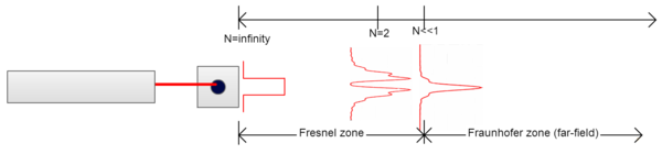
Starting from the beginning, diffraction is the bending of light as it passes around an obstruction. There are two main types of diffraction: Fresnel [near-field] and Fraunhofer [far-field]. The Fresnel number, N, is one way to differentiate between these two regions. It can be calculated using the r2⁄λL= N, where r is the effective radius of the diffracting object and L is the distance from the diffracting object to the imaging plane. Fresnel diffraction occurs close to the diffracting object where N ≥ 1, while Fraunhofer diffraction occurs effectively infintely far away from the diffracting object when N << 1.
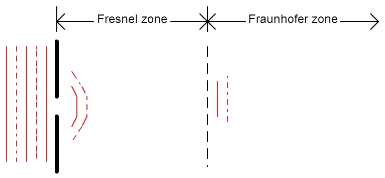
Fraunhofer Diffraction: Fraunhofer diffraction occurs when both the light source and the viewing plane are effectively infinitely far away from the diffracting object. The effectively infinite separation means that the wavefronts are effectively planar making adding up the contribution by individual wavelets simpler, which makes the math simpler. In the Fraunhofer zone, the diffraction pattern's shape and intensity are constant and independent of distance to the diffracting object.
Fresnel Diffraction: Fresnel diffraction occurs in the region immediately following the diffracting object. The shape and size of Fresnel diffraction patterns change rapidly as distance from the diffracting object increases. Wavefronts are not planar in Fresnel diffraction making them more mathematically complicated than Fraunhofer diffraction.
Fraunhofer diffraction is the more popular of the two because it is mathematically simpler and because the shape and intensity of the diffraction pattern don't change with distance from the diffracting object. Fraunhofer diffraction is often what is covered in introductory physics courses for the above reasons.
Diffraction from a Circular Aperture
In the Fraunhofer zone, the diffraction pattern produced by a circular aperture will be an Airy pattern, a bright central disk surrounded by concentric dark and bright rings. In the Fresnel zone though, the diffraction pattern from a circular aperture rapidly changes in shape and intensity.
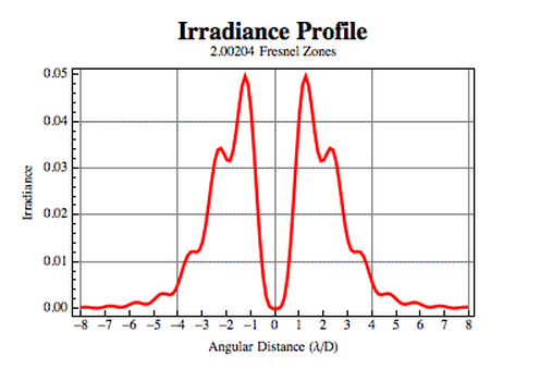
The Fresnel diffraction pattern resulting from a circular aperture has the unique feature of having an on-axis intensity of zero when the Fresnel number is even and four times the initial intensity when the Fresnel number is odd. Looking at the equation for the on-axis intensity of the Fresnel diffraction patterns formed by circular apertures, it is obvious why this is.
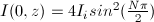
When the Fresnel number is even, the on-axis intensity will be a multiple of sin2(kπ), which is equal to zero and when the Fresnel number is odd, the on-axis intensity will be a multiple of sin2(kπ⁄2), which is equal to 1.
Lowell Wood's Paper: The Inspiration for my Project
In a 2013 American Journal of Physics paper, Lowell Wood proposed a method for creating aperture functions using the diffraction pattern from slits. Wood's method involved filtering the diffraction pattern from either a single- or double- slit, so that only the desired portion of the diffraction pattern is transmitted. Using this method, Wood was able to create a number of nonuniform aperture functions, which produced apodization and inverse apodization.
Apodization and Inverse Apodization
The goal of my project was to produce improved inverse apodization using Wood's method. Before I go into how we accomplished this, let me explain what apodization and inverse apodization are first and why they are important.
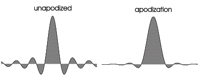
Apodization is a reduction in the amplitude of the secondary maxima of diffracted light relative to the central peak, while inverse apodization is an enlargement of the secondary maxima. Both are achieved by creating an aperture function with tapered transmission from the edges to the center of the aperture. In apodization, the central diffraction peak widens, while in inverse apodization, the central diffraction peak thins. Apodization is used in signal processing, photography, and astronomy to increase the signal-to-noise ratio. The thinning of the central diffraction peak in inverse apodization on the other hand produces super resolution. Super resolution improves the resolution of an imaging system beyond the diffraction limited value and is useful in nanoparticle imaging.
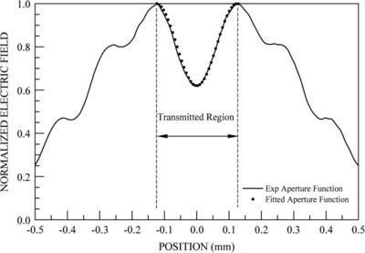
We were able to improve the inverse apodization that Wood achieved using a circular aperture. Inverse apodization is produced by aperture functions which have low transmission in the center of the aperture and increased transmission at the edges. Looking at the aperture function Wood used to produce inverse apodization, you can see that transmission is lower in the center and higher at the edges of the aperture. Inverse apodization could be increased though if the difference between the lowest and greatest transmission was greater. Recall from the diffraction from a circular aperture section, that the on-axis transmission when the Fresnel number is even is equal to zero. We took advantage of this property to produce improved inverse apodization by filtering the diffraction pattern from a circular aperture.
Experiment
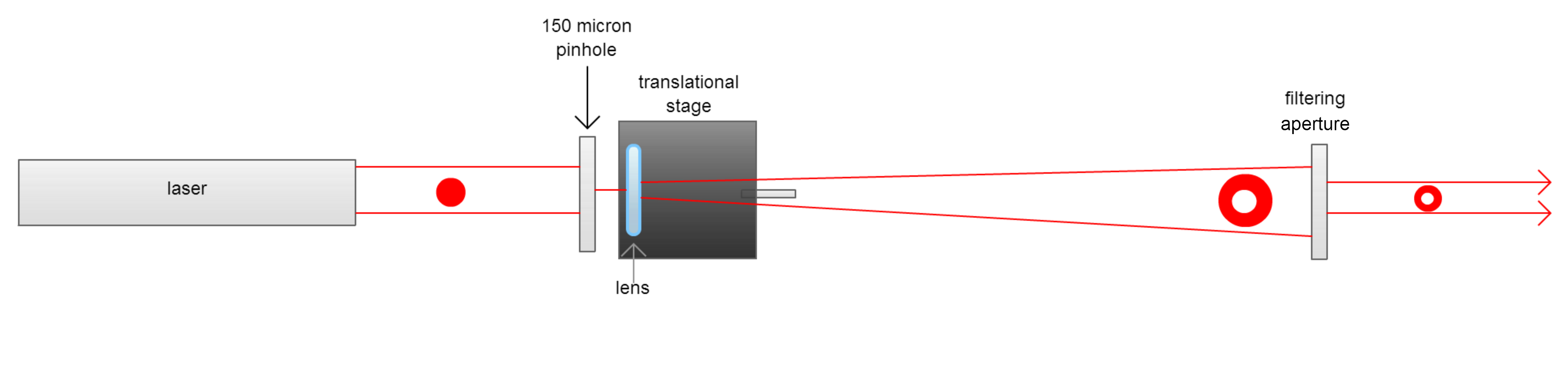
For our experiment, we passed light through a circular aperture and then filtered the diffraction pattern in the near-field using a second circular aperture when N=2, so that only the desired portion of the diffraction pattern was transmitted. Our reasons for choosing to filter the diffraction pattern at N=2 was three fold: 1) the even Fresnel number meant that on-axis intensity was zero, 2) most of the intensity of the diffraction pattern was in the first two peaks, and 3) the diameter of the diffraction pattern was the largest of the even Fresnel numbers because it is the farthest from the aperture, which makes it easier to see and align with filtering aperture.
Our set-up consisted of a HeNe laser, 150 micron pinhole, lens, translational stage, and filtering aperture. The laser beam first travelled through the 150 micron pinhole. The lens then imaged the diffraction pattern from the pinhole onto the filtering aperture. The translational stage allowed us to adjust the position of the lens finely, so that the diffraction pattern from the first pinhole when N=2 was in the plane of the filtering aperture. We hoped to use this method to observe super resolution and create improved optical vortices.
Super Resolution
Super resolution is a technique which improves the resolution of an imaging system beyond its diffraction limited value. Image resolution is ultimately limited by the diffraction of light waves as they pass through or around an object. This resolution limit is often referred to as the diffraction barrier, which restricts the ability of optical instruments to distinguish between two objects separated by a lateral distance of approximately half the wavelength of light used to image the specimen. The smallest separation at which you can discern two objects is the limit of resolution of the imaging process.
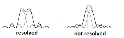
With super
resolution the central diffraction peak is thinned allowing for closer
objects to be resolved.
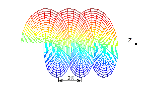
Optical vortices are helical beams with a dark center. They
vortices have a dark center because the light destructively interferes
at the center of the beam. These
twisted beams
have orbital angular momentum. The orbital angular momentum, ℓ, of
the beam is equal to the number of times the phase varies from 0 to
2π.
For this project, we generated a Lauguerre-Gaussian beam using a spiral
phase plate donated by RPC Photonics. Spiral phase plates work by
varying the thickness of a material with an index of refraction greater
than one as you
travel around the central axis because the index of refraction of the
material
is
higher than that of air, the light travels slower
through the material than through the air. This means the light that
travels through the thinnest section of the material will lead the rest
of the beam with each part of the beam that traveled through a thinner
section of the plate leading the beam travelling through a thicker
section. This lag causes the beam to form a helical shape.
We found that where the various thicknesses of material met at the
center of the
spiral phase
plate caused unwanted scattering. To minimize scattering in our
optical vortices, we passed a beam formed by the filtered diffraction
pattern when N=2 through the spiral phase plate. In the beam we passed
through the plate, the
intensity of the beam is equal to zero on axis and gradually increases as
you move away from the axis. We found that this method did not cause
improved optical vortices because the light continued to diffract from the
first pinhole even after passing through the filtering slit and the
filtering slit also caused a diffraction pattern. Even after removing the
filtering slit, unwanted rings would form in the center of the
Laguerre-Gaussian
beam.
We hope to model the Fresnel diffraction from the first pinhole as well
as the Fraunhofer diffraction from the filtering slits. We
are also interested in furthering our work on creating improved optical
vortices. We hope to use the method utilized in Will Weiss' LTC project to
create beams with zero intensity centers.
We thank Stefan Evans for
his
help modelling the diffraction patterns and teaching me the alignment
basics; Melia
Bonomo for her assistance in profiling and modeling an Airy pattern in
Mathematica; Liam Cavadini for his proof-reading assistance; and RPC
photonics (Rochester) for providing the VPP-633
vortex phase plate.
L.T. Woods, "Advanced optics experiments using nonuniform
aperture functions," Am. J. Phys. 81, 377 (2013).
C. Sheppard and A. Choudhury, "Annular Pupils, Radial
Polarization, and Superresolution," Appl. Opt. 43, 4322-4327 (2004).
J.C. Wyant. Fresnel Diffraction Pattern for Circular
Aperture
The University of Arizona, n.d. Web. 10 Aug. 2013.
Creating Improved Optical Vortices
Unanswered Questions and Future Work
Acknowledgements
References