Journal
Today I met all of those wonderful people working in the lab along with me. They are all very helpful and welcomed my presence. Dr. Metcalf and Paul Tchertchian have explained our project and we commence equipment gathering and building the OPTICAL TWEEZERS. I shattered a $100 first-surface mirror.
We continued our development of OPTICAL TWEEZERS. Entered mirrors to align laser into correct position (common directions). Used fully adjustable bases screwed to a level table. Used right-angle blocks and various size posts to elevate and shift first surface mirrors. Double-face taped mirrors to adjustable plates.
Again Paul and I continued our quest to develop working OPTICAL TWEEZERS. Today we collected more precise directions and added lenses to the system. On bases and fully adjustable post holders, we entered the lenses, however not in the correct positions (we had not yet added the diode laser, we were using a laser pointer and they are not the same, as the beam of the 780 nanometer near infrared laser is not collimated. It is however elliptical and this must be corrected as well).
Finally plugged in the diode laser. We observed that our power boxes were not working properly. Using a voltage meter and chart (that we found among other OPTICAL TWEEZERS projects), we found a safe operating voltage to be approximately 4 volts (for our laser only as every one is different). We then charted our findings of voltage vs. power (noting 50mW/mA) on Quattro Pro, which resulted in the graph we expected.
The graph was printed and resulted in near-perfection, except that the colors we chose to represent scales were very indistinct due to the use of a black-and-white laser jet printer. Later on, while testing our laser on the OPTICAL TWEEZER system, Lisa (a very helpful graduate student) instructed Paul and I on the preper safety and caution to be used while in the vicinity of a laser.
I have learned very basic HTML, with the aid of Molly Bright (our Bright student who knows DOS and HTML). Although I make alot of mistakes, I think these web pages should come out all right. Feel free to email me if I've made any drastic errors. Paul and I, after numerous hours of searching, found the digital camera and took about 15 pictures of our OPTICAL TWEEZERS setup.
Paul and I are having serious cylindrical lens problems. The directions we had instructed us to use two of these lenses, one with the bend in the horizontal direction and the other in the vertical. Well, for our purposes this setup only made the diode laser's beam more elliptical. After experimenting, we found that both lenses should be fully adjustable and bent in the vertical direction, resulting in an increase in the beam's vertical width.
We believe we have finished the OPTICAL TWEEZERS. Paul and I have not yet tested them but have already viewed hair and other small objects through our microscope/cctv monitor. The diode laser's beam width is the optimal size. On Monday we will prepare slides with test-subjects and begin trapping.
We began using polystyrene balls in our microscope configuration, excluding the laser.
We are mistaken in our observations. What we think are polystyrene spheres are actually only dirt particles. We have wasted approximately 18 slides (slide/wax/saple/coverslide/immersion oil/oil objective) and have exhausted our supply of immersion oil, which expired in 1997. The quest for immersion oil begins!
Today we added one more drop of poly-spheres to our 100 ml solution for a grand total of 4 drops/100 ml water. Using our microscope, we focused the spheres in our lenses yet, they do not jitter, jiggle, or vibrate. After hours of close observation, we learned about the vibrations of fat molecules in milk. Tomorrow we observe mil in our system.
We're only here until 12:30 so we got some whole milk, courtesy of the Harriman Cafe, and examined it. We noticed minute jiggling. That's about it.
Lisa (our TA) and I spend numerous hours slaving over a computer trying to rework my abstract, which was due last week. Also, Paul and I get disgusted after seeing milk left out from Friday. We head to the Harriman for another sample of whole milk, with which to observe fat particles.
Dr. Noe sent me an email last night saying that there was to be more revision the next morning. Paul and I arrived at the Laser Teaching Center at 9:30 am and I worked with Dr. Noe privately on the abstract. Meanwhile I am hoping that Liz Kelley (Simons Program Coordinator) isn't getting annoyed at the tardiness of my work. We finish around lunch time. After lunch, Paul and i set out for more milk, and then realize that perhaps we are not seeing any Brownian motion with our sphere solution because there may not be enough polystyrene spheres per droplet of sample (5 drops in 100 ml of water). We spend the remaining hours working on a sequence of math problems to calculate the average of spheres we should be seeing at any given time in our viewing area.
After learning more about objective lenses (our 100x oil immersion in particular) we have found that double-sliding is ineffective. Even though the focal depth of the objective is 2 mm and the top slide is only 1 mm, we could not see through the top slide clearly enough to observe microspheres. Also after numerous hours spent estimating the average number of spheres we should be viewing at any given time, we found that there could be anywhere from 1 to 25 spheres present in our viewing area. And, we discovered that 0.75 (actually 0.608) micron-sized spheres were too small. So began using 3 micron (actually 2.836) polystyrene spheres. We made up a slide (slide cover only this time) of the larger balls and were able to view them without any distortion. However, they were sticking together. Later this is corrected by adding detergent to the solution AND by making a Rose Chamber.
Using 1 drop of detergent in 300 ml water, we added a pin-tip of pure spheres to a few drops of the detergent/water mixture on a slide. It worked perfectly. Now we are able to actually see the spheres under the influence of Brownian motion. Dr. Noe also showed me how to use xfig, a precise drawing program on Linux, with which to model our setup for future presentation.
Last day of the Simon's Fellowship. We observed the Brownian motion of polystyrene spheres but were unable to trap any. Next week I will set out to focus our laser beam into the field of view.
I was at the Laser Teaching Center lab at SUNY Stony Brook all by myself. I begin my day by starting up the laser and observing some more spheres. After extensive online searches and many ponderous hours I still have not come up with a project for the OPTICAL TWEEZERS.
Today I finally received the shipment of immersion oil from Zeiss. It was sent almost a week ago "overnight mail" and was apparently lost. To focus the laser beam into the viewing area, I first started by turning the laser on and shining it through the lowest power objective (10x magnification). After finding the laser light focused onto a piece of paper (with a pen mark), I moved the dichoic mirror so that the beam was most intense near the center of the viewing area (looking at the monitor with the light source underneath the microscope off). I repeated this process until the beam was somewhat focused in the largest objective (oil immersion 100x). Now if only the laser's depth was focused in the same field as the focus of the camera! This is accomplished by focusing the ccd camera at infinity and by COLLIMATING the laser beam (all rays are parallel and so focussed at infinity, the same depth as the camera). I began making a model of the OPTICAL TWEEZERS setup.
I have trapped a yeast cell! The laser beam was not entering the microscope system precisely so direction and position into the aperture were recalibrated. Trapping is not fluent and exact yet. Power after loss due to all the mirrors? See November 16th entry.
I've been to the Laser Teaching Center a few times since October 31 but I seem to have run into some problems. The laser light shining through the objective is not coming off of the dichroic mirror perpendicularly and directly. Dr. Noe and I have aimed the laser more precisely. Also, trapping has occurred but is not consistent. I've been reading up on microscopy to figure out why i can bring the laser in and out of focus and why I see the image of a dot on the monitor in the first place. I believe it may be a reflection off the slide cover, either the top or bottom. Does that then mean, since it is also true that the laser must come to an acute focus just above the depth of the specimen, that I must trap objects that are below the depth of my field of view, or out of focus? It is also noted that when lowering the 100x objective into the immersion oil, it should be swung in at an angle to prevent bubbles from forming.
I have been seeing a reflection of laser light off of something because I am able to focus a white dot at two interfaces. Interface 1: boundary between bottom of slide cover/water (sample immersion). Interface 2: boundary between top of slide/water (sample immersion). This must be due to a difference in n, index of refraction. Water = 1.33. Glass of objective, slide cover, immersion oil, slide= approx 1.5.I have perfected the use of a Rose Chamber. In attempting this procedure, do not fill tub created by a hole in paraffin wax. Use only a small drop of liquid sample or else it will overflow onto the wax chamber walls and will not create the air-tight seal wanted.
Trapping has been inconsistent from the beginning. The beam entering the aperature at the back of the oil immersion objective is not entering vertically or at a 90 degree angle. Laser Tweezers were stripped down to the infrared laser only; Dr. Noe and I realigned all 4 mirrors at 45 degree angles. The position and direction of the beam is now corrected, as it is steered only by the 1st surface mirrors and not by any of the lenses.
The only remaining pieces in perfect order are the laser and 3 mirrors (excluding the dichroic mirror). It took many trials to perform current readouts after every mirror because the battery in the photodetector weakens at a very rapid pace. They were averaged and plotted. There was very little loss due to each mirror. Dr. Noe and I began analyzing several Gaussian bell curves, representative of possible beam radii (entering the aperture). We then plotted two graphs representative of optimum beam diameter in order to find and demonstrate the effects of both underfilling and overfilling of the microscope objective aperture by the laser beam.
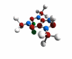
As I plan to enter Intel, I have spent much of my time writing essays and contemplating my research report. I compiled a list of parts and their specific details which are located on pages 17 and 18 of my Intel report.Caffeine Molecule
Tonight at 7pm was Kings Park High School's annual Independent Science Research Symposium. Present were administrators, advisors, students, parents, and teachers throughout the district. To give a little sinopsis of the event, the seniors plans, prepare, and host this night to give the disctrict a clear understanding of what our group spends its time and funds doing.Our research advisor Ms. Mary Ellen Fay opened the ceremony with a discussion of our groups success and a recognition of the administration. Jason Beiger, a good friend and fellow senior ISR student, the presented his project "The Design and Synthesis of Novel Anti-Cancer Taxoid-Porphorin Conjugates" first. Not only was Jason an Intel Semifinalist, but he placed first in the Long Island Science and Engineering Fair and went on to the International Science and Engineering Fair with his partner Christina Hung (Commack HS).
Students ranging from Freshmen to Seniors split up into their respective rooms to present their projects to large audiences Adelphi-style (with overheads or Powerpoint presentations).
Hors d'oeuvre are served before the ceremony commences and both coffee and desert conclude the night. This year, we hosted the largest Symposium, as over 100 people attended.
This year, we hosted the largest Symposium, as over 100 people attended.
I have been to the lab many times since November, both to work optical tweezers and to move my setup to another more permanent location in the Laser Teaaching Center. I entered the Intel Science Talent Search, which resulted in success: I earned Semifinalist status with an award of $1000 to myself and my high school. I then began competing physically with presentations of the project, entering in the Adelphi Junior Science and Humanities Symposium, the Long Island Science and Engineering Fair, the New York State Science and Engineering Fair, and Long Island Science Congress (see awards section). At Adelphi, presentations were either spoken in conjunction with overhead slide visuals or Microsoft Powerpoint. At the others, I used a backboard to present my project to dozens of judges through multiple rounds. Many judges were very excited with my work and I have since been in contact with a few of them.The 2002 Symposium went very well and our group was commended by the administration for our efforts. It looks as if funding for next year will be adequate and student projects will be substantial. Our 2002 Simons Summer Fellowship students soon begin their research here at Stony Brook University and I look forward to seeing them here.
This summer, I will remain in the Laser Teaching Center as a mentor/assistant. Basically, I will be organizing the laboratory, working with Dr. Noe, and helping students with their projects, while continueing my work with Optical Tweezers.
In order to facilitate my job, I have set forth a list of things to do this summer.
Organization
1. storage of mechanical equipment
2. storage of optical equipment
3. label drawers and shelves/master the label maker
4. mark all LTC equipment (red, black, white)
5. inventory lists of resources and equipment
6. grab bag of miscellaneous stuff
Structure
1. power outlets under breaker box
2. rearrangement of optical tables
A. move 1" hole aluminum table closer to wall
B. trade 2" hole aluminum table for 1" hole
3. find/buy rolling carts/electronics (shelved) cart
4. trade storage closet for shelved storage closet
5. buy opaque curtains to enclose 1" aluminum optical table
6. poster boards, cork boards, dry-erase boards mounted on walls
Personal
1. update webpage: journal, biography, divide into 2001/2002, add fair pictures, post resume
2. optical tweezers with Waldo
3. learn more Linux
4. play with fiber-optic cable
5. mount power sources for optical tweezers in box
Appearance
1. plan locations of backboards
2. develop mounting style-materials/purchase materials
3. choose backboards
4. construct
I have been marking components that were donated by a research group at Stony Brook Hospital with three pink nail-polished dots in a triangular pattern. I've also been organizing and labeling optics equipment and hardware. More later. Today our Simons Fellows were welcomed into the program and began their research. Good luck!
Yesterday and today I have been sorting through and seperating lenses, mirrors, and filters, and placing them in storage drawers. The lab has many of these drawers so filling them up will be difficult. Anyway, they are labeled and now much quicker to find.The Hospital had donated to us 3 matching Acopian AC-DC Power Modules, one of which I will use as a supply to my OPTICAL TWEEZERS. The models are DB15-30, 300mA modules and sell for approximately $125 (see Acopian webpage). They will replace te Lambda power supplies that are currently being used to power the laser box.
To better understand trapping theory, I have set out to further investigate ray optics and momentum.Newton's 2nd Law states: the change in momentum is proportional to the force impressed; and is made in the direction of the straight line in which that force is impressed. p=mv
The force exerted on a body equals the resulting change in its momentum divided by the time elapsed in the process F= /\ P/ /\ t
F=ma a net force applied to an object causes it to accelerate at a rate that is inversely proportional to the mass of the object a=F/m
Rayleigh Scattering (scattering involving particles smaller than a wavelength)
Trapping Forces- if the index of refraction n<1 trap is unstable since gradient forces will reverse direction
Ray Optics predicts maximum upward trapping for n=1.3. There is a decrease of trapping force at larger n resulting from a disproportionate increase of scattering force
PRACTICAL: n<1.3 due to large scattering force at high n tending to accelerate particles awar from the focus and make stable trapping more difficult.
About novacaine: Novocaine is the trade name for a drug that is rarely used anymore in dentistry it is a useful way of describing the local anesthetic and one that most patients readily understand. Local anesthesia involves the injection of numbing medication into the mouth. Once the medication has taken effect, the area will be numb and patients should not feel any sharp pain. Local anesthesia does not block the sensation of pressure which is sometimes felt during a tooth extraction.About General Anasthesia: V anesthesia is sometimes referred to as IV sedation and sometimes referred to as general anesthesia. Although technically not the same type of anesthesia that is given in a hospital setting for general anesthesia, patients have the feeling that they have been asleep for the oral surgery procedure without the accompanying nausea or malaise. IV anesthesia involves administering medication through the arm. In addition to the IV medication patients will also receive a local anesthetic (novocaine) once they are sleepy and unaware. This is done so that they will feel numb and pain-free once the procedure is completed.
This is very important. If you are getting your wisdom teeth extracted...and don't mind novacaine...DON'T think it will be enough to ease the pain of the remaining 7 shots. Since most wisdom teeth are either tissue, or worse, bone impactions, the needle must go very deep. Always, ALWAYS, take the general anasthesia. Thank you and good luck.
Waldo and I have been rebuilding optical tweezers at a much more vibration resistant height. Since the micrscope is so tall, it was necessary to construct a simple periscope in order to raise the laser beam to the appropriate height (to enter the back aperture of the microscope objective).We had taken the laser and cylindrical lenses out of the setup in order to take a picture of the beam, to analyze its shape, and determine whether the beam was circular enough (effect of cylindrical lenses). A conclusion has not yet been drawn.
Another interesting idea is to purchase an anamorphic prism pair -mounted of course- in order to circularize the beam. These are expensive but simplify the setup (~$300). Also, Steven Block's Contruction of Optical Tweezers mentions other lasers can be used, as long as they are TEM00, or single mode. This is someting to investigate.
I would like to get some pond, or better yet stagnant water, samples to view and trap.
Question: Why can I see near-infrared light with my naked eye?
Some Frustrations-I've been reading OPTICAL TWEEZERS articles for reassurance of design. I have so many problems that can be solved by using a different laser. The 780 nm near-infrared diode laser (sharp LT024) may be necessary in order to not damage the biological material being trapped, but I am not performing delicate cellular microscurgery. I'm trying to build a workable optical tweezers setup with optimum trapping power. This diode laser's beam is elliptical. That I've known for a year. Getting the beam to be round and collimated is not easy. The cylindrical lenses are accomplishing both tasks. I need an anamorphic prism pair. The collimating lens on the laser is not easy to adjust and still is not creating anythig remotely resembling a Gaussian beam. Every source I consult is different, concerning the laser, setup, and materials used. I have constructed working OPTICAL TWEEZERS but they are so weak due to a significant loss of trapping power. Not only is the beam being reflected off of 2 (removed a mirror-only needed to consolidate setup dimensions), but through 4 sets of lenses. Then, since the setup has been lowered for stability, I put together a periscope to raise the beam height in order for the beam to enter the objective of the microscope. So 4 mirrors and 4 lenses total. I need to perform another Beam Power Measurement to find the precise loss of power but it must be great. Then, since the aperture is so small (~6 mm) and the beam is overfilling it, there is another significant loss of laser intensity hitting the walls of the aperture. And still, the beam is not circular. A simple HeNe or Nd: YAG laser would solve all of my problems.
Today the REU students presented their projects. Congrats to all REU students and good job for all their excellent work.My sprained ankle is healing...apparently "hop-along" will soon be leaving the lab. I will continue to clean and organize the lab.
Wolodymyr and I have been reading Appendix I: Notes on Diode Lasers of "Lasers and Modern Optics in Undergraduate Physics," by John R. Brandenberger of Lawrence University.By his description of "diodes in the GaAs family, which lase in the visible and near-infrared," we guess that our laser is such. It is a highly divergent single mode laser, due to the cross-sectional dimensions of the active region being comparable to the lasing wavelength and according to the spectral profile, respectively.
The distribution of intensity therefor is not Gaussian, but rather corresponds to single slit diffraction:
I(theta)=Io(sin^2 B)/B^2
where B=(Pi d/lambda)sin(theta) and d is the slit width.
Home