Report
Introduction
My project idea came from this "flashy" sheet that was sitting on Dr. Noe's desk. It flips to a different image when looks at different angle. It reminds me of those little toys I played with when I was really young. Therefore I have decided that I will make one of those by myself. From the website Dr. Noe gave me I figured that those "flashy" sheets are called lenticular sheets. From this same website, he figured that we can ask for samples of those sheets to make our own images. In this experiment, we figured out the spacing of the images so that it will interact together.
What is a lenticular sheet?
In this faq section of the microlens company's website, they defined it as the following: A lenticular lens sheet is a clear plastic sheet with a special pattern (called a lenticular pattern) molded into one side and a polished flat surface on the other side. The lenticular pattern is an array of identical convex lenses designed to focus the light onto particular spots of the image on the back of the lenticular lens sheet. This focusing of the many lenses allows more than one image to be seen based on the angle of view through the lenticular lens sheet.
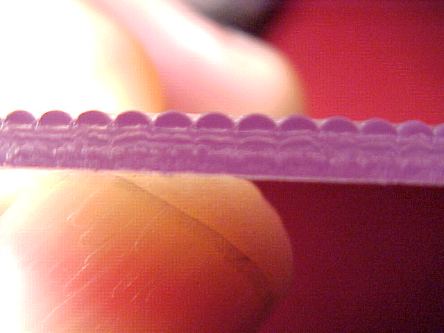
Following is a picture of the sample of lenticular sheet that we got from Microlens. The lenses are clearly shown in the picture.
The first experiment we did was trying to figure out how many time one particular image will be shown. The setup is shown below.
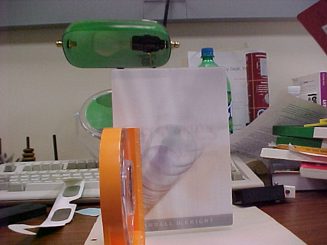
The lenticular sheet is taped to the orange protractor so that the pictures can be taken at different angles. After trying out many times, I figured that each image will appear 3 times in the 180 degrees range. The result is shown below:
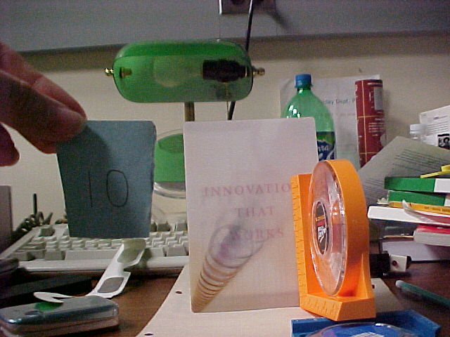
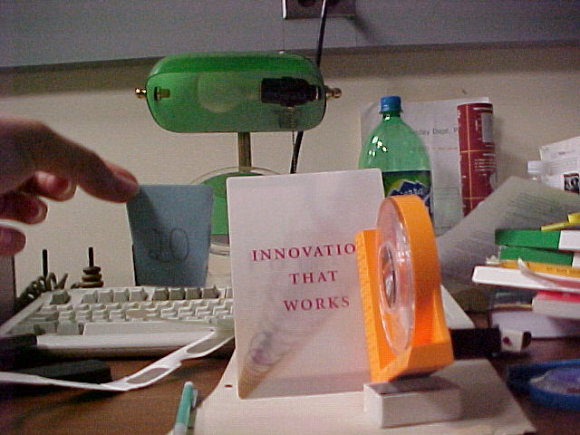

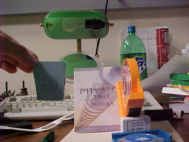
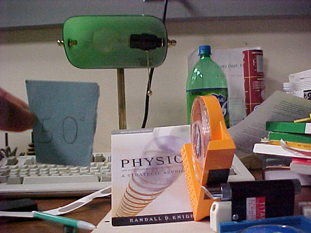
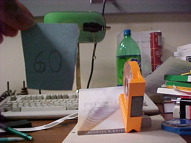
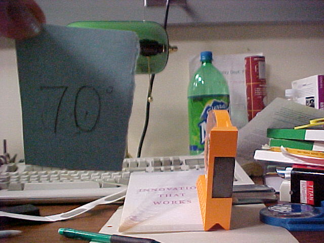
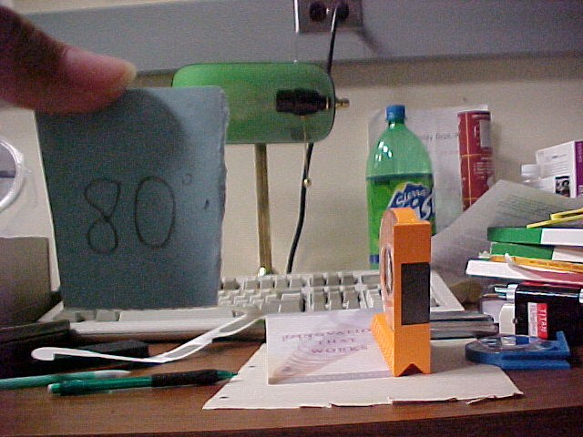
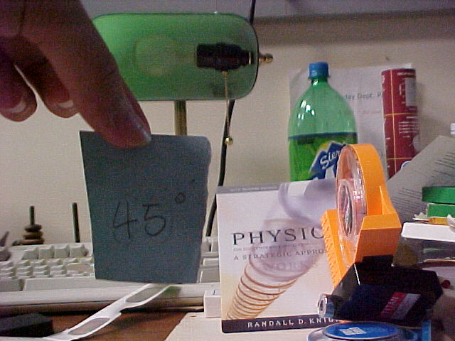
From the resulting pictures, we can see that the same image repeats 3 times in this range of angles.
The Second Trial
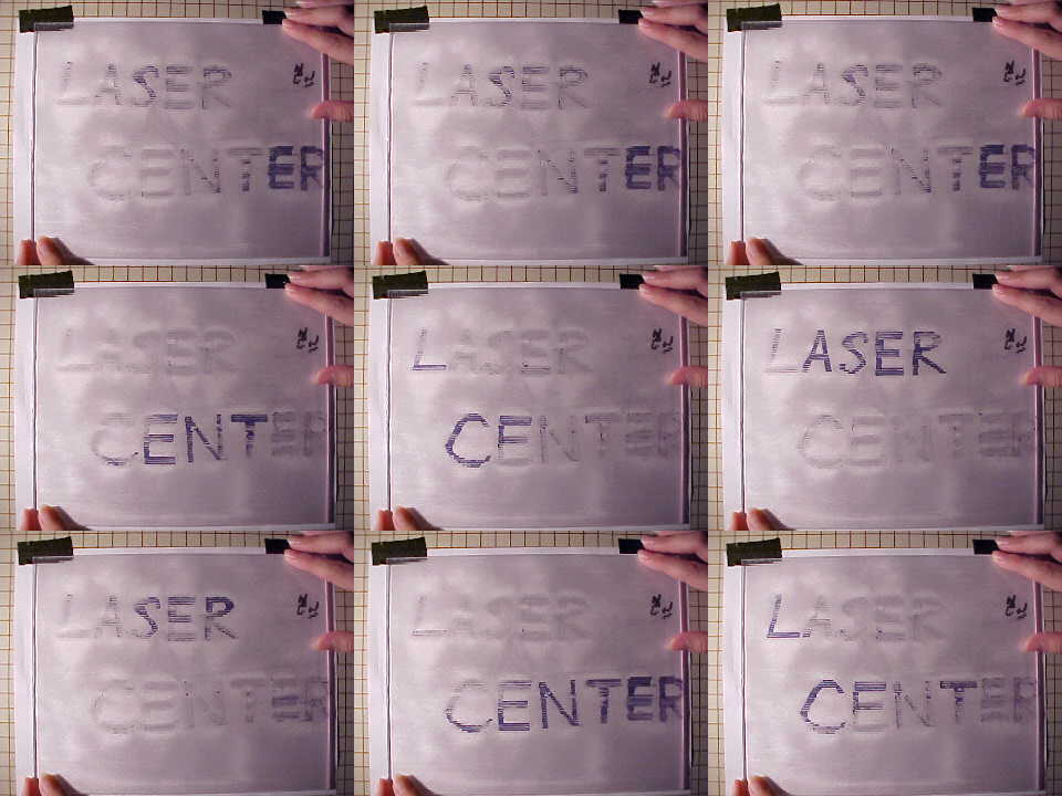
After the first trial, Dr. Noe told me that I can use the multiple mode of the camera to take a motion of the images of the lenticular sheet. The camera will take nine pictures during the three seconds. The result is below:
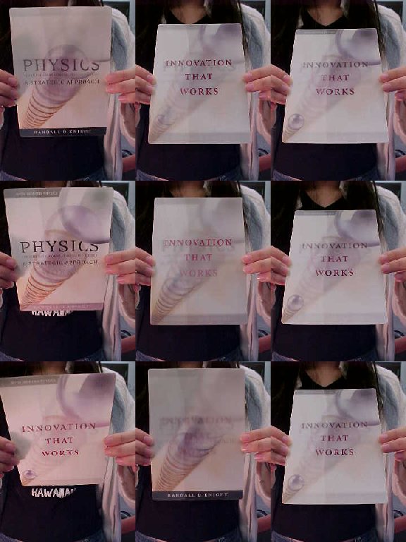
When put those pictures together, we can actually see the motion.
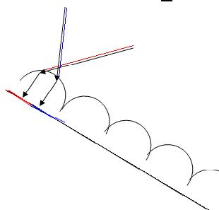
Imaging of a single cylindrical lens
Since the patterns on this sheet are convex cylindrical lenses, I went to the Physics and Astronomy Instructional Lab to borrow one of those cylindrical lenses. It appears to have this "flipping" effect when put on to stripes of different colors. These pictures are the set up and the results.
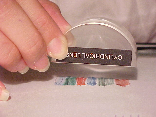
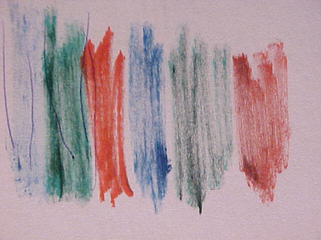
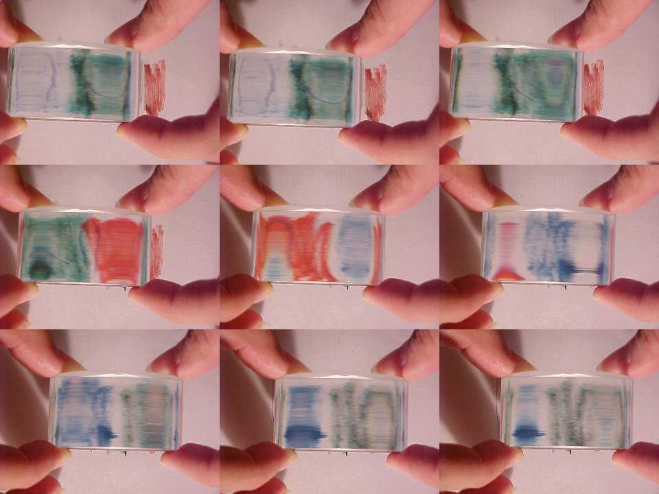
The lens was placed about 1 in. above the paper since that is the focal length of the cylindrical lens. From the resulting multishot pictures, we can see how the color we see from different angles is different.
The Color Changing A
Dr. Noe called this company called microlens to ask for information on lenticular sheets. They are very kind and they decided to give us samples of those sheets. Those samples came in all sizes. I decided to work with the 15 lens per in. one to make an image for it. Since the company didn't send us the program to make the image, I had to hand drawn our image. The following picture is an A that I draw to try to let it flips to different colors. From this trial I found out that the spacing between the two lines of one image is the same as the arrangement of the lenticular sheet which is 15 lines per in.
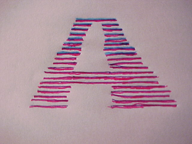
Following is the result
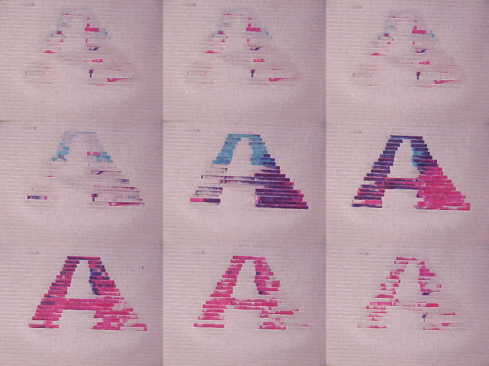
From the result we can see that the spacing actually worked and the A changed from pink to blue at different angle.
Another Trial
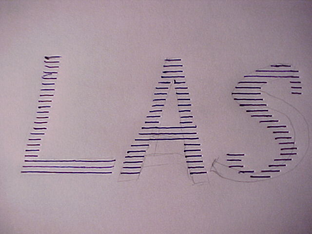
After the A, I spend a long time on a larger piece of drawing which was not as successful since its much bigger and requires much more precision on the arrangement of the lines. Below is my drawing and the result.
An interesting Discover
After doing all that work by hand, I figured maybe we can use computer to draw those lines since we know the spacing. Dr. Noe used this drawing program to draw a sheet of lines with 1/15 spacing. Since the program does not take integers while doing the spacing of the lines, there are errors to the diagram of lines. It does not all turn black when observed at a specific angle under the lenticular sheet. Following is a picture of it:
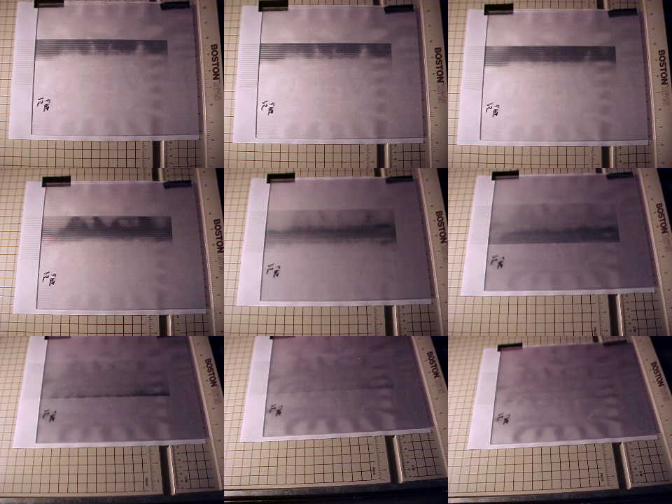
Since there are small errors on the spacing, the effect is not very well shown. Then, we had this thought that lenticular sheet can be used to find the precision of arrangement of lines. It can be used to find out whether the lines are drawn precisely at that spacing. The lenticular sheet will enlarge that error so tiny errors can be seen very easily.
| Nina
Han May 2008 |
Home Laser Teaching Center |