Cambridge Correlator's
low cost spatial light modulator
|
|
|
SDE1024 Spatial Light Modulator
The SDE1024 is a low-cost electrically-addressed liquid crystal spatial light modulator made by Cambridge Correlators. It contains a reflective LCOS (liquid crystal on silicon) display, which has a 62% reflectance at 633nm. The active area is 9.3x7mm with 1024x768 pixels (at 9x9μm each).

Image Source: Cambridge Correlators
The liquid crystal is in a twisted nematic mode. This means the molecules are aligned in a helical configuration with the first and last molecules perpendicular to each other. Light that enters with a polarization axis that is parallel to the entrance face will undergo a polarization rotation as it travels through the liquid crystal layer. As the light reflects off of the back surface of the SLM, its polarization axis rotates back to its original configuration, making this device effectively a phase-only modulator (since we cannot use polarizers to control the amplitude of incident light).
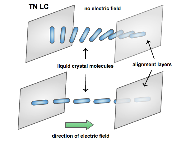
It’s a great addition to a teaching laboratory, however one issue is that it provides a very shallow phase depth – only about 0.8 Pi at 633 nm. This limits the types of projects for which we would be able to use the device, but not the many pedagogic benefits!
Example setup for optimization
Recently Marty found a paper by Padgett et al that described a method of optimizing the device in a setup where they observed the Fourier transform of various holograms on the SLM.
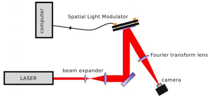
Image Source: Padgett et al (2011)
In the setup, a HeNe beam was expanded to fill the SLM aperture. The SLM was connected to a computer via a VGA input and addressed as an external monitor from a graphical programming code (they used LabView). A blazed hologram was displayed on the SLM and, by placing a lens in a 2- f configuration, a camera was used to observe the Fourier transform of the SLM’s output.
They used a “gratings and lenses” algorithm to create an arrangement of spots in the Fourier plane. A blazed diffraction grating will concentrate the maximum optical power in a certain diffraction order. The linear ramp configuration will produce a lateral shift of the spot, in the x or y-direction, whereas a Fresnel lens configuration will focus the light more sharply and bring about an axial shift, in the z-direction.
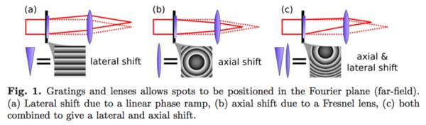
Image Source: Padgett et al (2011)
By combining a linear phase ramp and Fresnel lens, they controlled the lateral and axial position of each spot. There were also able to create multiple spots by adding individual holograms together.

Image Source: Padgett et al (2011)
Diffraction efficiency
Looking at a simple example of creating a hologram for a linear phase ramp to shift a spot in the x-direction of the Fourier plane:
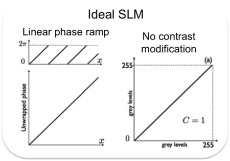
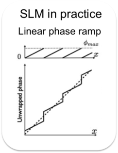
Image Source: Padgett et al (2011)
An ideal SLM would provide a constant phase shift such that a zero phase component corresponds to a zero grayscale value and a 2 Pi phase component corresponds to a 255 grayscale value. However, most SLMs have a maximum phase depth less than 2 Pi, which will correspond to the maximum 255 grayscale value. This results in an uneven phase ramp and an inefficient use of optical power (most of the light remains in the zeroth order, un-diffracted).
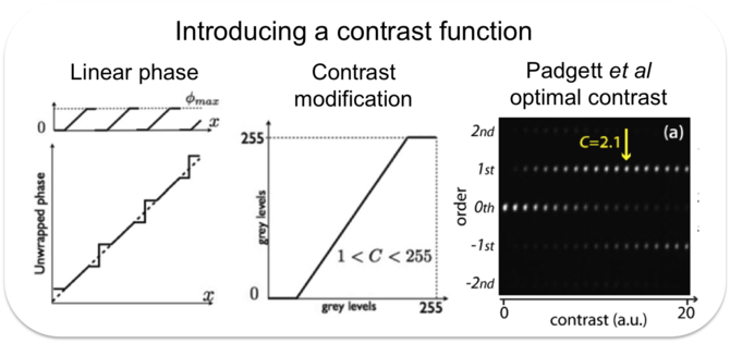
Image Source: Padgett et al (2011)
To lessen this issue, Padgett et al increased the slope of the phase ramp in the blazed grating by introducing a contrast function. This controls the number of pure black and pure white pixels. (For instance, a maximum contrast function would create a binary hologram with only black or white pixels). By choosing an appropriate contrast function somewhere in the middle, it is possible to create a phase distribution that was closer to the ideal. Padgett et al found that 2.1 was an optimal contrast modification which successfully brought out the first order diffraction and suppressed the others.
Suppressing ghost spots
When trying to create an array of multiple spots in the Fourier plane (for example, two spots in the first diffraction order), they used the complex addition of multiple individual holograms. This, however, creates a complex field often with extra, unwanted light spots known as ghost traps. The problem is that, in addition to the continuous vertical difference in phase, their “desired field” (for creating these two spots) contained a square-wave profile on the horizontal axis that can’t be reproduced with a phase-only SLM. Therefore, the SLM output looked as follows:
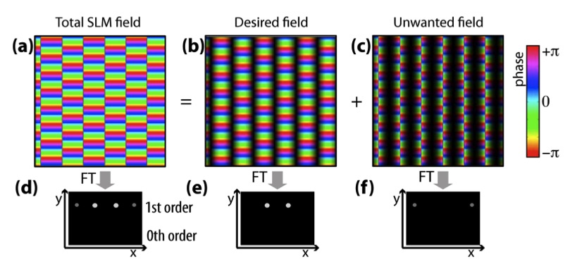
Image Source: Padgett et al (2011)
The high contrast between columns resulted in more high spatial frequencies being present in the first diffraction order. To correct for this, they created a phase profile on the SLM in which the phase contrast was decreased near horizontal phase jumps. Therefore, when they subtracted their “desired field” from the SLM output, the “left over” field contained very little phase modulation, as seen below:

Image Source: Padgett et al (2011)
The unwanted light is now concentrated in the zeroth diffraction order (i.e. not diffracted because low contrast means low spatial frequencies, which remain in the center of the Fourier transform). The overall intensity of the resulting first-order diffraction pattern is decreased, but it also no longer contains the unwanted ghost spots.
We can keep these methods for optimization in mind when designing our own hologram. Even with an SLM that has a shallow phase depth, we can improve the efficiency of the SLM by increasing the contrast in the blazing. We can also reduce the contrast in some areas to play around with amplitude modulation.
LM635 Collimated Laser

Image Source: Cambridge Correlators
The LM635 is a single mode fiber pigtail-launched laser diode. This low-powered laser module uses an achromatic doublet lens to produce a 24mm diameter collimated beam. The optical power is also adjustable by means of a potentiometer.
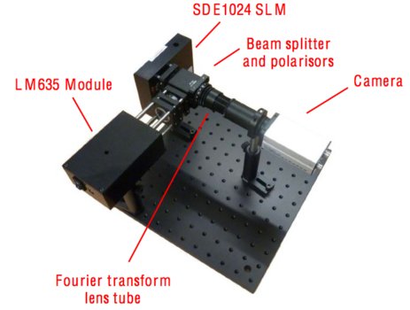
Image Source: Cambridge Correlators
The great thing about this is that we can create a nice compact setup with the SDE1024 SLM. Cambridge Correlators suggests the use of a Thor Labs cage and beam splitter, but we can set up something similar to Padgett et al by sending the input beam into the SLM at an angle.
References
Data sheet: SDE1024 Spatial Light Modulator
Data sheet: LM635 Laser Module
Padgett et al “Optimisation of a low-cost SLM for diffraction efficiency and ghost order suppression.” Eur. Phys. J. Special Topics 199, 149-158 (2011).