After Intel and the marathon of college applications, it's back to work on my project and its various tangents. I got here early in the morning - about 8ish because of work schedules combined with train schedules. Thank goodness for the new couch in the LTC, which allowed me to get some much-needed rest on the old couch placed outside.
Today Lindsey and Dr. Cohen were here for various reasons. A lot of time was spent on reviewing requirements and goals for LISEF with Dr. Noe, as well as some discussion on happenings in our respective research programs (we got a large-format printer for ISR! Woo-hoo! We also got a PCR machine, but that's bio so I'm not particularly interested in it.). The outlines I wrote during my absence helped to increase my awareness of what can and should be done, as did the overview of literature included in my Intel paper.
During lunch, Dr. Noe and I overviewed ideas regarding presentation as well as some currently unanswered questions in our heads about various aspects of my project. Various thoughts:
The current focus is on the relevant literature which may be overviewed in detail in my Intel paper. Should I pursue that tangent, I intend to include a substantial overview of the various methods of HeNe stabilizations, their pros and cons, in the attempt to construct a basic background of the topic.
Siemens is gone... now for Intel. Woo-hoo! I have exactly one week left to go, in which my paper needs to be mostly retooled and upgraded from something only partially resembling a good paper to something that actually IS a good paper. Should be a lot of fun. There's a talk scheduled for later today that I think I'm going to.
Despite what this may appear to indicate, I have been in the lab two additional times between August 19 and now, those being last Wednesday and yesterday. The focus? Getting more material for Siemens and getting the ball rolling on the paper. Results have been sparse, but the experience has relayed a great deal of information.
Yesterday in particular was quite interesting. We tried to build a PLD=10m Michelson setup with a mirror setup to relay the beampath around the table. For unknown reasons, adding extra mirrors to one arm spawned some optical gremlins in the interferogram. For example, pulling the third mirror straight back (lengthening the arm but not diverting the beampath) caused the long lobe to shift, but would not move the fringes; meanwhile, the other arm functioned normally. Strange. The setup also used a 6-in telescope to enlarge beam size and collimate the arms.
In the end, we're using pictures similar to those of last spring's project: PLD=2L images enlarged by a Thorlabs F=35mm lens and captured on graph paper with a mounted camera. The analysis should show fringe and intensity shifts using both graphs and pictures.
Correction: The on-off control from Wednesday IS on-off...well, it sort of is. The transistor turns off when the base voltage is negative, but allows variable current under variable positive voltage. I think this can be described with a case function, but I haven't tried it yet.
Today is my last day this summer.
7:30 PM: The laser is LOCKED! Dr. Noe and I spent a couple of hours experimenting with the 2N3904 and 2N3055 transistors and how to integrate them into the circuit, but eventually we managed to get the power supply to produce a current with them both in there. At that point, the oscilloscope readout of the error signal quickly stabilized at about +1.2 V. There was some minor flux from the system hunting for a more stable point, but beyond that the system was very stable. The power transistor is acting as a current regulator, something that the power supply showed rather clearly. Typically current stayed at about .05 A, with the occasional dip followed by a spike at .1A. Voltage from the supply was 15 V.
I'll try to get the diagram up later.
The on-off control I described yesterday apparently wouldn't be on-off control at all. Upon further review (with Dr. Noe), the schematic I drew is linear. Which, in this case, is better. Also, we spent about 20 minutes trying to figure out why the mode sweeping wasn't showing up on the oscilloscope before Dr. Noe noticed that it was set to AC and that we had been watching the signal noise. Way to go, me. Strangely enough, I can't remember ever using the oscilloscope for AC. Weird.
The warmup/cooldown graphs are officially finished and will be on my pictures page once I can get that up and running. I don't have a lot of spare time -- I want to get auto-feedback up and running in some form this week (even if it's poorly calibrated) because I need a paper draft for ISR when I get back to school. Deadlines...bah, humbug.
But on a positive note, the graphs look awesome. As in, at least as good as last year's data. It's a pity that this is just to characterize the laser action, because I don't know how I'm going to characterize the beam characteristics themselves...at least not until I build an SFPI sometime later this year. And how do I quantify my feedback control without that?
After graphing my data, I drew up a schematic for controlling auto-feedback with a transistor using signal polairity. A negative signal will cut off heater power, while a positive signal will activate the heater. Latency might actually work in my favor here, because the switching should eventually keep the heater at a relatively stable temperature, and the heat latency might keep the mode sweeping from accelerating to the point that the modes start jumping in and out of the gain curve. Hopefully that makes some sense. Either that or I need more sleep.
So far, so good: Measurements have proceeded smoothly. I set the heater for 1V and made measurements to model the effect of the heater on laser temperature. The time lag value in Newton's Law of Cooling was significantly smaller than yesterday's value, ostensibly due to the heater's location (secured to the outside of the laser tube).
Also taken were measurements of the cooldown to NOT (Normal Operating Temperature) after heater turnoff.
The lab seems empty...only Nilus, Lindsey, and I are here today. Dr. Noe gave me a key this morning after he showed up, which is nice -- now I'll get into the lab when I arrive first every morning. Hopefully I don't lose it.
I spent the bulk of the day taking measurements of the HeNe warmup curve and then fitting the data to Newton's Law of Cooling (adapted for heating). Incorporated into the fit was a time lag value to account for the heat transfer from the interior medium to the glass. The fit can be seen here.
I'm about halfway to auto-feedback, and ready to make some measurements. The next week should show some serious progress in the data area.
Manual feedback has been achieved!
I swapped the laser power supply out this morning, exchanging it for one that still works. Dr. Noe and I have agreed that 1W ought to do for heater power. That corresponds to a calculated value of ~4.207V from the analog power supply used to power the thermofoil, assuming that the 17.7 Ohm resistance given by Minco is correct. Being as I can't calibrate that by eye, I'll set the meter for voltage and calibrate the power supply with the (excellent) Agilent mulitmeter.
The Simons ceremony was today as well. I talked for a couple minutes and then got paid for the summer...which isn't the point, of course, but it's nice nonetheless. Dr. Noe confused me into bringing a suit to the ceremony, which proved to be completely unnecessary. D'oh. I have gullible written on my forehead.
I got in this morning to find the lab open but unoccupied. That is, I thought the lab was unoccupied until I noticed the electricians looking at a circuit breaker in the side room. Apparently one of the fluorescent bulbs was out and they wanted to make sure that it wasn't just a circuitry problem. In the end they just replaced the bulb and left, which concluded August 11, 2005: A Dead Fluorescent Bulb in the LTC Odyssey.
Matthias's thesis defence was today at 11 AM, and it was quite excellent. Prof. Metcalf was both impressed and proud (Matthias works in his lab). I especially liked hearing about how he did satspec to stabilize the laser. Satspec. W00t.
At around noon the defence ended. Marty Cohen helped me with the power supply I found the other day. I was confused as to why I was getting 0V DC but an AC signal at 60 Hz. This was easily fixed by using alligator clips to establish the proper connections to the power supply.
It was then noticed that the preamp inputs were sent across 100 megaohm resistors. To properly output my observed maximum current of 80 microamps would require 8000V! Diverting most of the current using kiloohm resistors to ground allowed the output of the amplifier to be manageable.
This setting, with both inputs set for DC, produced my desired output of a varying voltage with alternating polarity. With manual feedback achieved, I turned up the power on the thermofoil power supply to 5W (only about 1 percent of maximum allowed wattage)...and fried the laser power supply. The lesson was learned: Do not put a bunch of watts on something not designed to receive a bunch of watts.
Finally, Maaneli and I (and Nilus to an extent) helped Moon with her project. She now has an idea page with part of the concept for her project, and we began work on constructing the setup before I had to leave.
Manual feedback has not yet been achieved...but I'm getting closer! Nilus and I found a couple of ancient variable power supplies near the now-stripped optical tweezers setup, and we took one of them for the first attempt at manual feeback. This was connected to a Minco Kapton thermofoil attached to the laser tube using the adhesive on the back of the heater. It was hard to detect whether the heater was working because I haven't figured out where I want to attach the thermocouple to. Ideally we would have two, one for the thermofoil and one for the laser, but 1) I haven't figured out whether we have two thermocouples, and 2) I don't know how we would get a thermocouple to attach securely to the thermofoil. Something tells me tape would NOT be a good idea.
Jon and Danielle visited. I haven't seen them since LISEF! We celebrated by going to Lawan for lunch (thanks Dr. Noe!), soon after which I had to leave to catch my bus.
My abstract is finished!
Today was a wall of progress, not to mention a welcome relief from the stagnation that has plagued recent weeks for me. After a brief morning discussion with Moon about American politics (as an immigrant, she isn't quite as familiar with the differences between the parties) while we waited for an undergrad to come open the doors, Dr. Noe arrived and spent the first 90 minutes or so going over my abstract with me. It is now safely in the hands of Karen Kernan, which is undoubtedly a good thing.
Nilus has become increasingly involved in the project as of late despite his continued statements that he is neither involved nor knowledgable about the project. I got to flex my (relatively) newfound understanding of op amp operation by re-explaining the concepts to Nilus. In return, he helped me debug the system. After much speculation that the problem was in the circuitry, it appears that the problem was the laser itself. I (with Nilus' considerable help) devised a polarization test to determine what component(s) was/were faulty. After testing two multimeters to ensure their accuracy, I hooked each up to a detector and rotated the beamsplitter in increments of π/2. The maximum only oscillated from detector to detector when the beamsplitter switched, not when I left the system alone. One polarization is always the greater intensity. Therefore, the problem is the laser itself. Swapping in another laser solved this problem; however, I now need to remove the cover for this one (easier said than done -- I don't want to break it!) and adjust the axial orientation of the laser tube to achieve maximum variance and, by extension, maximum sensitivity.
The diagnostic had an immediate effect on my data readout. Previously, acting on my incorrect hunch that the op amp was the problem, I hooked the outputs up to a Princeton Applied Research Model 113 Preamp, which allows for variable gain control (I assume this operates by controlling a varistor substituted for the load resistor...altering, say, a varistor on one of the inputs would work also but would alter the ratio of the two input voltages as well.). At first nothing happened because the equipment was plugged into a non-functioning outlet. When that was corrected, I saw the same output as the op amp gave: an unvarying, unusually high voltage. However, after my diagnostic and repair, the system generated a wildly varying output. What the output means at the moment is something I'm not entirely sure of, but I would venture to guess that it's at least partially dependent on input, and that's an improvement.
This feedback system stuff is really starting to frustrate me. Up until this morning, I had always gotten the same result whether the photodiodes were on or off: about +300 mV with very little variance. I assumed that the problem was some incomplete wiring coupled with a gain resistor that was too large, and that the +300 mV wasbackground noise of some sort. However, today, after adjusting the cavity orientation to align it more closely with the polarization axes of the beamsplitter, I fixed both of my assumed problems. The new result is 300 mV of background noise which becomes 20 V on the oscilloscope when the components are turned on. This is read as 12 V on a voltmeter because that is the maximum a voltmeter can read. The problem? My op amp is only powered by 9V at terminal 4, with terminal 8 grounded. So where are the other 11 V coming from?
Another problem has to do with the input-output relationship. While having an input produces an output, different inputs all produce the same output. The result is a binary system with the photodiodes functioning as an OR gate. If either one is on, I get 20 V. If both are off, I get 300 mV. It seems that the residual voltage of the batteries, when amplified, is enough to produce the 20 V output of the op amp. How and why this is are questions that remain unresolved.
In this instance, I don't have any reference to tell me why the system ISN'T working. I already know how it's supposed to work, but I can't reproduce that system on the circuit board...speaking of which, I don't trust this circuit board quite as much as I used to. 11 rogue V aren't supposed to show up from out of nowhere. Maybe my ground is at -11 V?...but that would mean that I would read 11 V without an input. This is so confusing.
Of course, there's always the possibility that I'm just too exhausted to think rationally, and that more sleep would reveal an obvious solution to the problem.
Later...
Well, one question has been resolved without really answering anything. The 20 V I read was actually just a screen reading displaying the scale of the oscilloscope boxes. The boxes were set to 20 V each. With this knowledge, I reread the voltage at 12 V...but then when I turned off the power, instead of reading 300 mV, I found the voltage climb to 30 V! The confusion just got worse from there. I checked and rechecked my circuit, but found no loose connections anywhere. How a higher variable input multiplied by identical gain could yield a consistenly lower output baffles me.
Well, at least I'm making some progress. Things are moving too slow for my liking, however. Feedback systems are easier to visualize on paper than to actually build. I'm hoping it's just a simple thing like a loose connection.
Today was the REU presentations, and was also Maaneli's and Greg's last "official" day. The presentations were very good, just as we expected.
On the work front, however, progress was slow at best and nonexistent at worst. My circuit refuses to work. Bah, humbug. Sooner or later I'll figure this out.
Finally, my abstract is done and sent to Dr. Noe for review. After he reads it and sends it back to me I can format it and send it to Karen Kernan.
The Simons tour was awesome. It also consumed most of the day. I spent a good part of the morning setting up the polarization demo (getting the right concentration of Cremora in the water was harder than I thought it would be...I put about 30 times what I needed in at first) and then had to run and grab an early lunch in order to be back for the 1 PM start time.
Everyone presented well (Nilus keeps telling me I presented well, but everyone did a good job, so hopefully he's telling everyone they did a good job). Dr. Noe commented later on that there were no factual errors made, and yet the presentations didn't sound scripted. Maaneli's technique of using an analog as a method of explaining something in simpler terms is something that I picked up on during the REU tour, and it made me much more comfortable. Prof. Metcalf used the analog of driving a car down a straight road to explain feedback systems, and that in particular was useful. Liquid nitrogen stole the show, however, as the other Simons students crowded around Amol & Co. as they attempted to freeze various objects and observe the effects. Greg determined that nitrogen-cooled water tastes excellent.
Also, Moon needs to stop focusing on the PowerBook and get an iBook, which is much cheaper and fits her needs much better.
Other notes: The specs for the HeNe power supply and pumping system are as follows:
Variable Power Supply: Hewlett Packard 6284A DC Power Supply
Laser Pumping System: Laser Drive Inc. Model (134)006-1013738
Recommended Operation: Input DC 10-14V at 0.9A, Output DC 1250V at 4.0mA
Today I began to run into problems with my circuitry. In the morning I made good progress with the help of Dr. Cohen, who was a big help in deciphering the Zener diode portions of Laser Sam's schematic (apparently they are the internal components of my photodetector that make it more than just a basic photodiode). This enabled me to ignore certain parts of the circuit and focus on the more relevant ones. We also discussed certain components of my circuitry and what their respective functions were. There was minor confusion over how the internal structure of the photodetector output its current and voltage, but that was resolved (I was correct!) after a brief check of the Thorlabs schematics for the DET110.
The problem, however, is a large one: My input has nothing to do with my output, which indicates either that I have a gain problem or that my circuit has an inherent design flaw. A gain problem merely requires me to swap out a couple resistors for different ones, but if the circuit design as a whole is incorrect the fix will be more comprehensive. Unfortunately, I can't fix that tomorrow, as we have the Simons tour to prepare for -- not that I mind the Simons tour, I'm actually looking forward to presenting -- and that will take up the majority of my time tomorrow.
This cracks me up: The Wikipedia entry for Microsoft's supposedly "next-gen" OS, Windows Vista, states that the new OS will sport a "completely re-designed user interface". That's right, they said completely. Which, I believe, implies that the interface would look, well, different. How different does this look? That's right: not particularly different.
Better yet, the article states: "The most visible addition to the interface is the sidebar (however this feature has been removed in the last alpha release and Beta 1 release), an area at the side of the screen consisting of tiles which display dynamic information about whatever window is currently in the foreground, which is essentially an extension of the "system tray" on the Windows taskbar." Or, in other words, the interface's most prominent new feature isn't even being implemented. Sounds like this is a big update. (sarcasm off)
Poking fun at Microsoft aside, the day was both fun and productive. I made some real progress with circuitry today, although I still need to determine the polarization axes of the emitted beam, which is a separate problem altogether. Planning for the upcoming events was done during the weekly pizza lunch. In the afternoon I did more circuitry work, attached the thermocouple to the laser cavity, and saw a superconducting magnet in action.
After a quick check and search, I found that the photodiodes on the beamsplitter setup are Hamamatsu s2386-18L's, which are sensitive to visible and near-IR, with peak response at 980 nm. The diodes aren't ideal, but the sensitivity at HeNe wavelength is about 65% of maximum, which is good enough for my purposes. More important is that both diodes are the same.
The wiring on those diodes is driving me insane. I would much rather use the Thorlabs DET110 detectors that we have in the lab. After setting those up, I noticed that one detector's maximum readout intensity is always 3x or 4x that of the other detector, regardless of setup, battery, etc. I can't figure out why. Equally disconcerting is my observation that the circle-shaped linear polarizers in the back room appear to be incapable of allowing more than 20% of light through. I cannot proceed without rectifying both of those issues.
The wheels are in motion. For next week: Set up and achieve manual feedback, get to work on the auto-feedback, and get materials for the Fabry-Perot.
I got here late today because the DMV was painfully slow in issuing me my permit. Bah, humbug.
My understanding of the SFPI is as follows (thanks to Laser Sam): An etalon is set up, with the laser beam entering on one end and exiting on the other. The exiting beam encounters a photodetector. A ramp waveform is generated to drive a PZT on one end of the SFPI, adjusting the length of the etalon by a factor of a few λ, and the detector response is viewed on an oscilloscope. This images the active modes in real time, with resolution of at least one part in 107, and most likely better than that.
Sam gives an example of a red (~632.8 nm) HeNe entering an SFPI of d=80 mm and mirrors with 99% reflectance (R). In this case,
| Δλ = |
|
= 8 ⋅ 10-15 m |
|
which, relative to the 632.8 nm of the red HeNe, corresponds to approximately 6 MHz. |
|
This value is determined by Δλ = |
|
, where FSR (Free Spectral Range) is given as |
|
and F as |
|
. |
In a paper in Optics Letters by Notcutt et al. from JILA and the University of Colorado, the SFPI was mounted in a vertical structure for damping purposes. The effect of the damping was to allow a Fabry-Perot cavity to achieve resolution on the order of 1 Hz. Perhaps I could achieve something similar with a homemade one? It's something to consider.
Dr. Noé reminded me today of Laser Sam's Fabry-Perot scanning etalon. This could be used in conjunction with an oscilloscope to get a live visual readout of mode spacing, intensity, etc. The concept sounds useful.
The thermal feedback portion of my project is now underway. I found the Minco thermofoil and set up a half-exposed HeNe tube paired with the soldered polarizing beamsplitter and detector platform. When this gets up and running, I'll probably start off with manual feedback control before inserting the auto-feedback circuitry. You have to crawl before you can walk ^.^
The CMM tour was today. I'm not much of a bio person, but I did find the NMR stuff to be somewhat interesting - the whole concept of oscillating magnetic fields generating AC currents to locate individual pieces of proteins is interesting, particularly because I'm an E/M person - so it wasn't exactly boring. I just like it better here in the Cave ^.^
The cleanup/setup effort which began yestrday afternoon hit full throttle this morning. In addition to rechecking my organizational skills, which worked just fine yesterday, I setup a polarizing beamsplitter-detector system (soldered in Prof. Metcalf's lab) to work with a HeNe. Of course, the entire feedback portion of the system is disconnected, but the setup was at least good for viewing mode sweeping: Due to the orthogonally polarized modes in the short-cavity HeNe, the polarizing beamsplitter sorts alternating modes, so the majority intensity alternates between one diode and the other.
José joined us for a late lunch at Jasmine, after which we took a brief tour of his lab.
Following Dr. Noe's suggestion from last week, I've read up on polarization spectroscopy, primarily in Laser Spectroscopy: Basic Concepts and Instrumentation by W. Demtröder, and found it to be described as more effective than satspec without any substantial increase in difficulty. If that understanding is correct, then that's the direction I want to go in. I know the pieces I need to move forward with the project, so now it's merely a matter of getting the necessary materials and beginning construction.
Amol got the streaming coverage of the Discovery launch to run on the Windows machine in the back, and I plugged my headphones in to work as speakers, so we got to watch the launch live with sound. It was some pretty cool stuff...or rather, pretty hot ^.^
After lunch Dr. Noe and the rest of the lab started working on the giant cleanup job that needs to be finished before noon tomorrow for the REU tour. I spen tmost of that time reorganizing the massive resistor bin by color code. Now it won't take 5 minutes to find a couple of resistors -- more like 30 seconds.
Today was somewhat of a slow day -- not much was going on -- but i did get some work done. Among other thing, I started transcribing Nilus' optical lever report into XHTML (he would do it himself, but he has band camp this week). The group had a brief (hour or so) discussion about paper-writing and how every word should have a purpose. At the present moment we have finished the introduction and constructed an "experiments table" which details the varibles defining each experiment.
I thought I was ready to implement the satspec setup, but it turns out I didn't know the first thing about it. Now, well, I have reason to be confident. Hopefully next week I can start building the setup, but that's a hope, not a certainty. What determines what I do next week is primarily whether I can get my hands on all the components I need.
We got started right away today. Maaneli, Dr. Noe, and I proceeded to simplify yesterday's expression to
| IL= |
|
|
At 11 Prof. Metcalf gave us a talk on op amps and diode lasers, after which we went to lunch at a Thai restaurant in Patchogue-Medford. The food there was excellent -- Dr. Noe apparently knows his restaurants (thanks for the food, Dr. Noe!)-- but we were there for a pretty long time and we ended up spending close to 3 hours away from the lab.
Amol and I went on the Simons trip to BNL this morning, which was a lot of fun. We saw the Van de Graaff, the STAR detector, and a small piece of the NSLS. I was very impressed by the STAR detector (it's huge!) but personally found the LINAC here to be more impressive than the one at BNL -- the SBU LINAC is more imposing, what with all the external wiring and all, even despite being about 4 million volts weaker.
After returning and eating lunch, I went back to the op amp work I did with Maaneli. We attempted to make a brief presentation on the op amp, but eventually realized that our answers to the questions Dr. Noe was posing were rather incorrect. After about 2 hours, I found myself with a much stronger concept of how the op amp actually works. Maaneli and I then proceeded to (re)derive the equation relating output current to input voltage in the given circuit (we got Il=(V5/R5)-(V1/R1).)
In this entry, I will try to put down everything I know (or think I know) about satspec. Hopefully I know more than I think I do.
Laser output is controlled by a number of variables, two of which are cavity geometry (temperature-dependent) and input current (dependent on the power supply). By modulating these two variables, laser stabilization can be achieved.
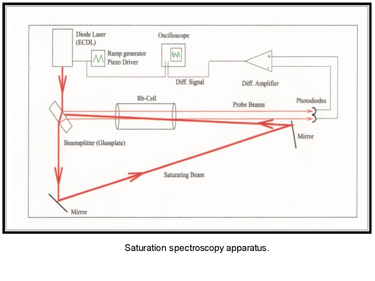
In iodine satspec, the laser beam is split into a majority (saturation) beam and two minority (probe) beams. These beams are redirected to travel through an iodine cell in opposite directions. The saturated beam overlaps one probe beam while in the iodine cell, but not the other. If the frequency does not properly match a hyperfine transition of iodine, the excited atoms will be traveling at velocities of either +v or -v, dependent on the direction of the beam. However, because the beams are traveling in different directions, they are exciting different atoms, and thus both probe beams are attenuated. On the other hand, if the frequency properly matches a hyperfine transition of iodine, then the saturated beam is exciting the same atoms that the probe beam is trying to excite. As a result, the attenuation of the probe beam decreases, which causes an increase of the detected intensity of that probe beam.
Two photodetectors, each amplified (typically by a low gain AC signal amp) feed a lock-in amplifier, which takes the derivative of the absorption peak and converts it to an error signal. A dither signal replaces the saw-toothed "ramp" signal, which was previously scanning over the absorption peaks, and allows the circuit to precisely locate the top of an absorption peak. The dither is what drives the PZT, which alters cavity size, causign a change in the input for the lock-in amplifier, which alters the dither, etc, in a circular pattern.
The convoluted dither signal reentering the lock-in amp is filtered and sent through a phase-sensitive detector, then filtered again to create the error signal. Because the error signal must be DC (otherwise it would be filtered out), it is imperative that the dither frequency stay small enough to focus the peak scanning over an area where the second derivative of the peak is as close to 0 as possible.
Given this scenario, any drift to either side of the peak will produce a significant error signal, which will cause the PZT to either contract or expand, returning the laser to its original size!
In other news, Amol and Greg got the adjustible spiral phase plate to work very well, even despite dirty mirrors and all sorts of other stuff that messed with the interferometer. After some brief discussion, it became quickly apparent just how many projects could be derived from that plate. People are starting to mobilize...I had better get moving on this before I get left in the dust.
I will need the following components for the HeNe satspec project:
Or, at least I think that's what I need. The best way to figure out what is and isn't necessary is going to be setting everything up and then troubleshooting. Of all these materials, I think the LTC has everything except for the iodine cell, the lock-in amplifier, the generator, and the PZT (we might have the PZT).
Some things I have to remember about satspec:
I spent just about the entire day (minus the Metcalf "clocks" lecture, which was awesome even though I've heard it before) attempting to derive the equations for inverting and non-inverting op amp circuits. After a discussion with Dr. Noe, it was realized that negative voltage in the inverting op amp is allowed (hence the name). With that knowledge, the rate at which the formulae came along increased quite rapidly.
Wow, birthdays are fun. I went out to a good Chinese restaurant yesterday (yes, that was an obligatory food reference) and got some cool stuff, including a Chelsea FC jersey. I also spent a lot of time learning Inform, which is a programming language used to write cross-platform text-based videogames. Thankfully, the terminology and syntax for that appears to be fairly straightforward, so hopefully I'll have enough of a handle on the language to start writing games as a hobby before long.
But back to the subjects I'm supposed to be talking about. Dr. Noe is back from his trip to the Suzuki Institute in Ithaca, and had some interesting optics-related material and stories to show/tell us. We then hurriedly rescheduled tomorrow's pizza lunch for today (can't anything ever stay on schedule?) and I ran around telling all the various people who need to know about pizza, some of whom I had told earlier in the day that the lunch would be Tuesday. Bah. 'Twas a mess, but it was cleaned up quickly enough.
We had a fairly brief visit from Dr. Rafailovich and a couple of students from the Garcia Center. Greg was in the back cracking Plexiglass to make some adjustible spiral phase plates, which prompted a discussion of optical vortices and a demonstration of the Sagnac.
During lunch everyone discussed their projects with Prof. Metcalf. I mentioned my interest in satspec and also talked about how my project could prove useful for Amol. Prof. Metcalf said that spatial coherence is an issue, and also said that projects requiring long spatial coherence length often isolate the beam in some manner. Perhaps some design involving a vacuum contained in a pipe to allow the beam to propagate freely through space would be useful for Amol. I don't know...maybe PVC with flat optical-quality glass on both ends, it would have to be something hard-sealed or something along those lines I suppose. That's an engineering problem ^.^ always a nice aspect to any project.
I now have a focus: satspec. I also have a good amount of source material and a basic understanding of what it is that I'm trying to do. The next step, therefore, must be implementation. We'll see how that goes next week. But for now...well, it's my birthday this weekend.
Everyone should learn to play Mao. It's a card game. I would include a link to the rules, but unfortunately the only rule I can tell you is this one.
I spent the morning looking at Bob Azmoun's report on satspec, and found a good part of it to be surprisingly coherent. That's progress of a sort. The circuitry is still confusing, but I'm making some progress, and hopefully it should be more understandable later on.
In the afternoon we did some cool stuff with a Sagnac interferometer (used in gyroscopes) and liquid nitrogen. After aligning the interferometer, we took a number of brief intermissions to (carefully!) observe what happens to various objects after one freezes them. To our surprise, we made a rubber ball (which oreviously didn't bounce) become incredibly "bouncy".
Oh my God, it's Colossal Cave Adventure! Seriously, it's the best game ever:
matt@laser:~/public_html/2005_06/journal$ adventure
Welcome to Adventure!! Would you like instructions?
noYou are standing at the end of a road before a small brick building. Around you is a forest. A small stream flows out of the building and down a gully.
Just try and beat that. Unfortunately I have to restrain myself from playing it or I wouldn't get any work done here. But I can save it for another day, another place...maybe there's a version that will run on my iBook.
I spent the morning using the RadioShack ELL to construct logic gates. I then took the individual gates and combined them to make chains of gates in both series and parallel. After lunch I advanced to transistor circuits, which confused me until I realized that the orientation of the transistor was important, unlike the orientation of a resistor.
The specific things I made:
- Simple AND gate with switches;
- Simple OR gate with switches;
- Inverter (NOT gate) with relay switch;
- AND / NAND / OR / NOR gate with switches and relay;
- YES transistor gate with DPDT switch;
- NOT transistor gate with DPDT switch;
- AND transistor gate with switches;
- NAND transistor gate with switches;
- OR transistor gate with switches;
- NOR transistor gate with switches;
These circuits were constructed while referencing Digital Logic Projects: Workbook II by Forrest M. Mims III, pages 14-21, although for the most part I was able to construct the circuits without having to refer to the diagram. After the first couple circuits things got somewhat more intuitive. The thing I'm still having trouble with is looking at the board and translating the curved wires and components into a diagram in my head. One really doesn't look much like the other. I also don't get why an AND transistor gate is better than an AND switch gate. Is it a size issue, or is it the desire not to have as many moving parts, or what? The diagram certainly looks a lot more complex and confusing, and as far as I know that's not exactly a desirable quality.
I guess that the reason I'm using the ELL is because I honestly don't know much about how circuitry works beyond the bare minimum taught in Regents-level physics, and because that's not going to cut it if I have to develop a feedback system. If I'm going to use electronics in my project, I should take the time to develop a decent base of knowledge. Electricity is some cool stuff, but at this point it's still not something I'm comfortable describing...which is somewhat shocking (pun not intended) considering that none of my work over the past year-plus would be possible without it. So this is something long overdue.
To clarify: Moon and I spent a good portion of the day tinkering with the RadioShack Electronics Learning Lab, making things with integrated circuits. Among our creations: a random number generator, a tuneable noise synthesizer, and a comparator. We also added extra LEDs to the random number generator, which made the kit look rather like a Christmas tree, but covered in plastic instead of pine needles. The real reason for building stuff was because we don't understand how the things in the ELL book work yet, so building them step-by-step according to the instructions should help us at least get acquainted with the different parts of the ELL. Later in the week I can try building things without constantly consulting the manual.
Jan gave a good talk on X-ray microscopy at today's pizza lunch. We have the same birthday (July 17th), so next Tuesday we'll have our birthdays at lunch. It should be fun. The German grad students were teaching Moon some German, although I doubt they were being perfectly honest about the definitions they supplied. That's just a hunch based on my experiences trying to learn Cantonese from some of my friends. Teaching someone German isn't supposed to be that humorous.
Random thought on Amol's project: How stable does his laser have to be? If he's trying to encode phase information and transfer it over long distances, doesn't the light source have to be ultra-coherent?
I said in my "Week in review" that I wanted to get to work on my major project. Well, it turns out that I'm getting to work on someone's major project this morning. It just isn't mine.
But seriously, Amol's project, even though it's just in the planning phase, is getting even more incredibly awesome every day. It involves OAM sorting and reminds me of Stanley's quantum bit project from last year. I was talking to Amol outside this morning during a fire drill and he mentioned needing something to generate vortices. Dr. Noe had shown me a paper titled "Adjustible Spiral Phase Plate", and it seemed relevant, so I gave it to him to read. It turns out that that is almost exactly the sort of thing he was looking for. So now he's looking at the Michelson set up in the side room. Meanwhile, he says he needs something to rapidly vary the α produced by the phase plate. Perhaps some sort of feedback-controlled stepper motor setup with high and low threshold voltages - a Schmitt trigger setup - would suffice. Of course, there are two things I haven't figured out regarding that idea:
But, of course, this is distracting from my real purpose today, which is to work toward an experimental setup for MY project. I printed out and stapled a number of papers on feedback control of the HeNe.
|
|
I'm moving in the direction of iodine stabilization. It still involves feedback, but with a piezoelectric transducer (PZT), and it's much more reliable.
I've also been looking at saturated absorption spectroscopy as a possible application to use for the second half of the laser stabilization project. Satspec is an important part of MOTs, and there is some work which has been done with it in the LTC before. But it seems kind of silly to stabilize the laser with iodine and then do satspec on iodine...I mean, if I've already stabilized the laser, then what exactly is the point of doing satspec? It's redundant. So if I'm using the iodine/PZT setup, then satspec doesn't seem to make much sense.
The siesta is over. I have to start zoning in on stabilization and figure out what method I will be using. Until I do that, I can't even begin to think about what sort of application I want to use the laser for.
Rain. That was what we had today. Lots and lots of rain.
Around noon we went to the SAC for lunch. The rain came, it came down hard, and it wasn't planning on leaving while we were eating lunch. A little after 3 in the afternoon, we finally gave up on the rain ceasing and made a mad dash for the physics building. Of course, the rain stopped about a minute after we finished that quick run.
In the lab, we spent a lot of time doing riddles with Greg, who has some real brain-busters. I also talked with Marty Cohen about how whispering-mode lasing works.
And my interest in laser stabilization has grown to encompass all variants, be they feedback-driven or via the use of an iodine cell or whatever. It's all good.
I have completed the diagrams from yesterday. So here goes my attempted explanation of the "θ-->2θ" problem:
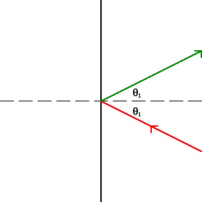
Fig. 1: Reflection at mirror position 1 |
Figure 1 is fairly straightforward. The incident beam, oriented at angle θ1, undergoes specular reflection and is reflected at an angle θ1.
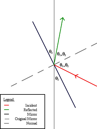
Fig. 1: Reflection at mirror position 2 |
In Fig. 2, the mirror has been rotated θ2. The incident beam is now at an angle θ1+θ2 relative to the normal, and therefore is reflected at at an angle θ1+θ2 relative to the normal. The change in the total angle between the incident and reflected beams as a result of changing the mirror position by θ2 is (θ1+θ2+θ1+θ2)-(θ1+θ1)=2θ2. Therefore, a change in mirror position of θ yields a change in reflected beam trajectory of 2θ.
The "pitch" or threads per inch, of yesterday's screw is still up in the air. The trouble is either the data or the equation. Nilus's equation yielded a result of about 5.3, and I calculated 26.98. The actual answer is probably around 40. This afternoon, Amol and I attempted to rectify the situation once and for all, but only managed to generate an answer of over 55. Bah, humbug. After the attempt, I noticed that there is an indentation in the back of the mirror where the screw makes contact, which could have something to do with the inaccuracy. Why? Because if the screw's position changes by x as a result of rotation r, but the mirror position is changed by a smaller distance y because the screw isn't making solid contact with the mirror, then the measurements don't reflect how far the screw was actually moving. While I doubt that this situation was actually the case, maybe it was. But then what are we getting wrong?
There was a Simons meeting today in the Honors College room on the third floor of the Melville Library. The room was about as far away from a stairway as possible, which made it difficult to find. The talk given by Prof. Simmerling was interesting enough (it wasn't a physics talk, but it had a decent amount of computer science in it, which is always good).
Apparently people stayed here late yesterday to work on polarizer problems. Unfortunately, I had a bus to catch and couldn't stay late, which is decidedly not cool. Oh well. There is always the next day.
The matrix war is raging now. I told Amol that his matrices didn't show up on any of my browsers at home and he responded by saying that "your browsers are out of date." Which they are not, of course, but it's a good response. Nevertheless, if the MathML only shows up on Mozilla Firefox (it hasn't shown up yet on anything else), and my code shows up just fine on any browser, well, that speaks for itself. Looks like I win. (Watch, now he's going to just make his code so much better than mine that I can't even compete.)
Greg is back after his single day of jury duty. Everyone go say hi to Greg.
I found a paper on lasing in microspheres which appears to be fairly comprehensive. Perhaps if I go through this paper and learn about the various concepts discussed or referred to I will gain a significant enough knowledge of the whispering-mode laser to include it in my project.
The measurements taken by Nilus, Moon, and Maaneli were input in Quattro Pro today, then analyzed and graphed in a manner similar to the way I analyzed my Gaussian profiles last year. The fit this time was much easier, due in part to the fact that a straight line is simpler to fit than a complex curve. The results came out OK, with the one flaw (sample size) being corrected as I type.
The goal of the project on which the lab was working today was to determine the thread density of the screw on the back of the mirror used in yesterday's optical lever experiment. A lively and spirited debate broke out about whether changing the angle of the mirror by Δθ produced a change in beam trajectory of Δθ or Δ2θ (The correct answer, for the record, is Δ2θ). We then derived the equation used to calculate thread density and went to lunch.
For tonight, I want to draw up the diagrams from today from scratch and email them to myself so that I can download them here and put them in my journal. If I succeed...well, we'll know by tomorrow.
I should note a few things about optical amplifiers before I forget.
The op amp obeys the input-putput relationship
V0=A(V+-V-) where V is the output voltage, V+ and V- are the respective input voltages at the non-inverting and inverting inputs, and A is the amplifier gain. For the ideal op amp, the following two statements are true:
a) A=∞
b) R=∞ for both inputs.Therefore, for an ideal op amp,
1) V-=V+;
2) There is no input current.1) can be seen from a). If A=∞, any finite voltage becomes infinite when amplified. In practice, the gain is usually about 106 with a input difference of μV. Similarly, 2) can be seen from b). With finite V and infinite R, Ohm's law states that there must be no current.
That op amp information and more can be found here. I'll put more up later when I start drawing up the schematic for my feedback system. In the meantime (read: over the next week or so), I plan on learning basic LaTeX so that I can eventually put the schematic up here for all to see.
Now that July has really started (I know, it started last Friday but we only had one day of it in the lab), it's time to get down to work. The morning was spent in a Metcalf lecture on matrices and non-commutative transformations, which are used to detail the effects of polarizers. The lecture was the usual length, no more than 90 minutes, but after Dr. Metcalf left we went to work on the board in an attempt to derive the matrix transformation effected by a polarizer of any angle θ. The result was:
|
|
= |
|
Deriving the above statement involved diagrams I haven't figured out how to draw using HTML...at least, not yet. Speaking of which, Amol has implemented some really nice-looking MathML in his journal to combat my messier but more interesting (IMO) nested tables. He's declared a matrix war as well.
The homework assigned was to determine all matrices A which satisfy the condition A2=I, where I is the identity matrix
|
Prof. Metcalf said there were 4; however, after a few minutes I noticed that all matrices of the form
|
where a=(1/b), satisfy the condition.
Also from Prof. Metcalf: "`Telling a child how to eat his dinner is not commutative. Saying, `Go eat the pea and carrots on the plate' is not the equivalent of `Go eat the carrots and pea on the plate.'" Which, of course, is now immortalized in my bank of physics jokes (who knows, maybe I'll make a page of them for people's viewing pleasure).
The whispering-mode lasers I touched on last Friday seem somewhat related to the base part of my project. The internal path of the light being totally internally reflected around the inside of the whispering-mode cylinder must have an integral-λ path length. If I can lock the HeNe in single mode and then tune the mode to a λ satisfying that condition, I can pump the whispering-mode laser. Perhaps a possible project could be creating a macroscopic model of whispering-mode lasing (whispering-mode lasing has microscopic applications because the size of the cylinder or sphere can be very, very small) and pumping the laser via a stabilized single-mode HeNe. The single-mode stabilization requires a different type of circuitry than the one I've been looking at...perhaps a Schmitt trigger would be useful. I could have the heater turn on when the low mode disappeared and then turn off when the mode increased to a greater (but still small relative to the intensity of the other mode) intensity. The effect of the smaller mode, would hopefully be negligible given the aforementioned circumstances. This, of course, is speculation, but until I look at the physics of whispering-mode lasing in more detail (unfortunately, I can't find much in the way of an introductory webpage on the topic. just published papers), speculation is about the best I can do.
This first week has been much different than last year's. I haven't jumped right into a project the way I did last year with the thin lens mini-project, but I think that the opportunity to spend more time asking questions and talking about whatever I'm thinking of has helped me know this group well more quickly than last year. I need to come up with an application for a mode-stabilized laser.
Taking the train home yesterday was useful (and not just because it let me grab a bite to eat across the street from the train station). Amol helped me finally figure out the puzzling polarization demonstration from yesterday's Metcalf lecture. After a bit of math, I came to the following conclusion: For a vector of magnitude n encountering p polarizers oriented at θ relative to the polarized beam, the magnitude of the resultant vector R is given by the equation
| R=x cos2pθ |
For example, if a vector of magnitude 100 encounters 3 polarizers, each oriented at θ=π/4 relative to their respective incoming vectors, then
| R=100 cos6 |
|
=12.5 |
Yesterday's homework was the definition of a number...A number is any element of an integral domain.
Also from yesterday was the following awesome paradox:

Yes, it's true: Pictures are up from yesterday. Enjoy.
Isn't it crazy that, while eiπ=-1, that halving θ to π/2 produces ei(π/2)=i ?
For lunch today we went to the Curry Club (thanks, Dr. Noe!). As usual, thefood was excellent. While eating we realized that a surprising percentage of the group was vegetarian. Amol brought up an interesting idea about the creation of a circular laser, which apparently already exists and is called a whispering-mode laser.
Q: What's better than one lunch?
A: Two lunches!
Well, technically I ate breakfast and then lunch (I don't eat breakfast in the morning), but it was still good. We went to Jasmine for lunch again today, and it was filling again. It makes me doubt that the food is actually Chinese food, even though it tastes like Chinese food (prompt Matrix quote: "...maybe they couldn't figure out what to make chicken taste like, which is why chicken tastes like everything.").
Anyway...today we had the first "Metcalf lecture" of this summer. The lecture was quite good, and focused on a topic that we've spent some considerable time covering: roots. We went over rules of roots and how using logic to try and do certain normal mathematical functions can lead to traps. How do we know that the square root of -1 is i? What is i? For that matter, what is a number? If a number, as Dr. Noe said in response, is "something which you can compare to another quantity and say is bigger or smaller," then is i a number? Sure, we say it's an imaginary number, but saying that 2i is bigger than i doesn't really say anything, because i isn't a measureable quantity in the first place.
Even more puzzling is the idea of complex conjugates. (1+i)(1-i)=1+i-i+1=2; that, as Dr. Metcalf said, is the logical equivalent of combining oranges to make them disappear. Complex numbers behave the way they do only because i is defined the way it is.
That being said, they are pretty.
Something which I've done before, but which was demonstrated in the lecture as well, was the derivation of eiπ+1=0 via definition of the infinite series for eiθ:
| eiθ=1+iθ- |
|
-i |
|
... |
| cosθ=1- |
|
+ |
|
-... |
| i sinθ=i(θ- |
|
+ |
|
...) |
| eiθ=cosθ+i sinθ |
| eiπ=cosπ+i sinπ |
| eiπ=(-1)+0i=-1 |
| eiπ+1=0 |
In the afternoon Greg and Maaneli drew special relativity problems on the board:
|
A man atop a tunnel wishes to trap an oncoming train in that tunnel. At rest, the train is bigger than the tunnel. To the man atop the tunnel, the train is moving at close to the speed of light and has become smaller than the tunnel. To the man driving the train, the tunnel is traveling at close to the speed of light and has gotten smaller. Which man's perception is correct? Can the train be trapped in the tunnel? |
Hüygens' principle is now firmly embedded in both my notes and my brain. The math involved mixed partial derivatives though, which was not fun considering I don't have much of a calc background. After about 90 minutes I managed to work the math out step by step, which is decent enough, I suppose.
This morning was slightly more reminiscent of last year's revolving door of people. Dr. Winters and Dr. Cohen both were here. I knew both of them previously, but the rest of the group did not so they introduced themselves. Around noon the group went with the rest of the REU students to visit the nuclear structure lab. I had never seen the LINAC itself (although I had seen both the computers and the Van de Graaff), and the tour was both informative and entertaining, so I enjoyed the visit.
Jasmine is a strange place...I've gotten full on Chinese food before, but I've never thought of Chinese food itself as filling. Today's food was. Strange.
The various reference pages are full of useful information but each one has different information and is organized differently. I'm starting to work on compiling all this information to create one massive menu. Currently it's in the early stages of construction. When it is finished it will be located here.
Hüygens' principle continues to bug me for some unknown reason. The concept doesn't jive with my previous understanding of wave propagation. Then again, I never had a great handle on wave propagation in the first place, so that could explain why Hüygens' principle seems iffy as well. Hopefully some more studying tonight will yield results.
The morning was somewhat more math-oriented than the day before, which was refreshing to say the least. The Gaussian intensity distribution was touched on briefly (needless to day, I'm rather familiar with that), as well as odd/even functions, the small angle approximation, methods for calculating unknown values of radicals, etc. An interesting question was raised by Dr. Noe: What pattern is created by double-slit diffraction from a lightbulb? The answer: Because the light being diffracted is both variable-wavelength and variable-phase, there is no pattern (technically speaking there IS a pattern, but it is unstable and not clearly defined, as opposed to coherent monochromatic light, which produces a clearly defined, stable pattern). However (this I did not realize), double-slit diffraction of single-slit diffracted light from a monochromatic incoherent source DOES produce a stable, clearly defined diffraction pattern.
Previous to this discussion session, I reorganized the picture directories under a new comprehensive directory that will serve all years. I expect that this reorganization will help down the road when I accumulate more files during the progress of my next project. The lab calendar has also been updated and does not need to be reset until the conclusion of Simons.
During lunch I talked to Maaneli about Tesla. Maaneli related to me one of Tesla's theories, this particular one dealing with gravitation. He didn't get into specifics, but I think it would be something worth looking at, perhaps tonight or tomorrow.
The rest of the lab now has accounts and web pages, which I will link to once material begins to accumulate in them. While this was being done, I noticed that Greg has made a good Linux reference page...I have to remember to add it to my weblinks later, and maybe print it out for my notebook.
In the afternoon the lab group used a spring to create different types of waves (transverse, longitudinal, torsional). At one point Greg and Amol generated a wave which alternated between longitudinal and transverse. Thus, we had created a coupled oscillator. Dr. Noe was impressed. I tried to replicate the wave later on and the spring detached from the coat hanger and almost hit me in the face. Amol said that the sound was similar to a Star Wars sound, i.e. the sound of a biaster firing. Yes, that was excess information.
For tonight/tomorrow:
The first day of Simons was very interesting. The day started with an informal breakfast at the SAC where I got my Simons materials and met Amol, the other Simons student in the lab. The other students are:
After a talk from Dr. Noe (about 90 minutes or so) about the lab, what we'll be doing over the next few weeks, and some order of magnitude review (including yotta*yocto=1), we got lunch at the SAC, and Amol and I got our ID cards from the Admin building. The afternoon was spent mostly in darkness, observing and discussing fundamental optics concepts, i.e. reflection, refraction, diffraction, interference, polarization, absorption, emission...basically everything essential. This was all transferred into my notebook later on.
Also, tomorrow will be one year since I started working in the lab. Woo-hoo!
Finally, there are a couple things that need my attention sometime tomorrow. One is that I need to reorganize the picture directories to account for there being a second year. The other one is that the calendar in the lab is stuck back in April/May! Hopefully tomorrow I can get that back up to speed.
Today was very, very busy and interesting. For starters, I entered the LTC and saw Jon Estrada and Co. (a friend of mine from elementary school) on a tour. There was also a visit from a Chinese professor whose name escapes me. He is apparently staying in a chemistry lab for 6 months on a paid visit from China. I talked to him for some time about the lab and my experiences here.
But more importantly, I redesigned my LTC page! All the stuff from 2004-05 is on a separate page. When Simons starts I will move over to this journal and continue with regular updates. I'm also reversing the order of posts, so this one (the oldest) will be on bottom as has become conventional here.
