For the next couple of months I will be working on a new project that deals with flattening the intensity spatial profile of a stigmatic laser beam. I will be helping Joerg Bochman, one of the visiting students from Wirtzburg to construct a setup that will allow us to flatten the spatial profile of the beam. This beam will be used in the bichromatic forces experiment on Prof. Metcalfs lab which also will be the basis for Joerg's master thesis. Currently an astigmatic Gaussian beam is used in the experiment. However, atoms traveling through this Gaussian beam see a intensity gradient. The exact reason why this is not the optimal situation I dont fully understand. I believe that atoms traveling through the center of the beam interact more with the beam since its the region with the most photon density. Better interaction between the traveling atoms and the beam would occur if the beam had a flat intensity profile.
There are many methods that we can use to achieve the flattening. Some methods waste a lot of the initial intensity. For instance, we can pass the beam through an aperture that will cut away most of the beam except for a central region chosen because it does not change too much in intensity. Then we can expand the beam to increase this area. The problem of this approach is fairly obvious, we are throwing away over 50% of the initial energy. Another method uses a specially designed absorption filter to flatten the beam. This filter works by having the most absorption at the center of the filter while tapering off in such a way to match the decreasing intensity of our gaussian beam. Both these methods waste a lot of the initially available light.
We also considered other methods that do not throw away so much light or even nothing at all. For instance, we can use a combination of aspheric lenses to flatten our beam. The magnification of the rays entering near the axis is greater compared to the rays entering near the edges. This results in a redistribution of the light intensity from the center to the edges of the beam. This system can accept up to 99% of the light while generating a smoothly varying output beam. This method is the basis for a new commercial product by Newport. Their refractive beam shaper offers high efficiency and a large range of wavelengths that can be accepted by the device. However, the cost of the beam shaper runs in the thousands of dollars. We thought about constructing a similar device from scratch. The main problem from carrying out this idea is that the aspheric lenses needed must be custom made to fit a particular shape defined by the characteristic of the beam. The manufacturing of such lenses would cost the same than buying the Newport beam shaper. The usage of aspheric lenses continues to be appealing since its the method that will most efficiently transform our Gaussian beam to a flat-top shape. In practice what these lenses do is to shift part of the light intensity to the sides by having a magnification radially dependent. What this means is that the part of the beam passing through the center of the lense is more magnified compared to parts of the beam going near the edges of the lense. With the proper lense shape, the Gaussian profile of the beam can be evenly distributed to create a flat distribution.
Joerg came up with the idea of using multiple beam overlapping in such a way such that the added intensities add up to a flat profile. To accomplish this we thought about using birefringent materials such as calcite that have different refractive index depending on the polarization of the incident beam. For instance, calcite has two orthogonal propagation axis (slow and fast axis) each with different index of refraction. A linearly polarize beam at 45 degrees from these axis will be separated because the components of the beam will propagate with different speed (propagation in a medium is related to the reffractive index). This results in two beam exiting the crystal with orthogonal polarizations. If you cut the calcite crystal in a particular geometry, you can have these two beams propagating parallelel with each other and you can even control the degree of separation. If these beams overlap, their individual intensities will add up. By adding multiple beams you can have them add up in such way that the combined intensity will apear as a flat top (or so we though). The efficiency of the beam addition and etalon flattening scheme was compared and appears that we can keep more of the initial light intensity with this multiple beam process. There was a problem with this scheme, first each beam and its neighbor will have orthogonal polarizations. This will cause a problem with the atoms as they cross the beam since they will see these regions of different polarization. Second, the regions where the beams overlap will have a dip in the intensity. This is because the intensity adds as the square of the electric field and in the overlapping region you will have a factor of square-root of 2 (due to the equal field magnitude where they join) to deal with. Multiple beam overlap to flatten the profile still is one of the most elegant solutions. However, we still need to work on a setup that will solve the previous problems.
The method that we are strongly considering for the beam flattening uses the angular dependence of the transmission fucntion of an etalon to flatten our beam. We can use this angular dependence by using a divergent laser beam. Our proposed setup will consist of a keplerian telescope to change the wait of our initial beam and a low reflectivity etalon. Since we want to use the zeroth order of the transmission pattern, the beam will be perpendicular to the surface of the etalon. The telescope comes in handy when trying to match the angular range of the beam with the angular acceptance of the zeroth order of the transmission pattern.
The transmission function of the etalon depends on the reflectivity of the etalon, the refractive index of the etalon material, the thickness of the etalon, and the angle of rays of the beam with respect to the normal of the etalon. Since the reflectivity and thickness of the etalon is constant, we decided to use the divergence angle of the beam as our free parameter. More importantly, since we want to use the beam divergence to fine-tune the fitting of gaussian beam with the transmission function, we chose a region near the waist of the beam since in this region the divergence of the beam changes is not constant as compared to regions away from the waist where the divergence is more or less constant.
The main problems from using the etalon to flatten our beam is that the transmission function is highly sensitive to changes in the optical path of the beam through the etalon. For instance, we need to specify both the flatness and the parellelity of the etalon. Flatness we see as how rough the surface of the etalon is. Most companies claim that they can achieve a flatness of better thatn lambda/20 which in our case is 54 nanometers. However, even changes of 20 nanometers in the optical path length can change the intensity of the zeroth order by 10%. On the other side, these changes in surface flatness occur on distances much more bigger than the size of our beam. So, we can have some leeway on accepting these kind of deffects. Also, the surfaces of the etalon cannot be made arbitrarily parallel and if we could extend the surfaces towards infinity, we could see that they will touch eventually forming a wedge. Parallelity is a measure of the angle of this wedge and the lower the value of this angle, the better the parallelity is. Manufacturing deffects are not the only source for changes in the optimum optical path lenght. Factors such as temperature can change the transmission of the etalon zeroth order by as much as a percentage per degree of temperature of variation. Other of the problems that can arise from using the zeroth order is that reflections from the etalon surface can cause feedback on our laser. However, we believe that this can be easily solved by placing an optical isolator before the beam passes through our telescope.
Another problem has to do with the geometry of our beam. The zeroth order of the transmission function will give us flattening on both axis of the beam. However, the beam that we are working on is astigmatic. This means that one axis is bigger than the other. We think that the solution for this problem is not to use the zeroth order of the transmission function, but to use instead one of the higher orders of the etalon. These higher orders appear as a "series of unequally spaced parallel stripes instead of rings".
We started to test the ideas we had from Mathematica simmulations to actual experiments. For instance, we rigged a setup that consisted of our light source, a expanding and collimating telescope and an etalon. Since we could not work yet with the ultra-flat glass plate that we wanted, we settled with a glass cover plate borrowed from the Weinacht's group. At first we tried to observe the transmission pattern produced by the etalon placed at the beam waist. However, we were not able to observe anything. We think that the intensity changes were present but they were too faint to notice. Then we decided to observe the pattern produced by the reflection from the etalon's face. A problem arose by trying to observe the reflection, we could not view the zeroth order pattern. This is because the zeroth order can only arise from rays coming perpendicular to the surface of the etalon. Such rays will then be reflected back to the laser. We settled by just observing the relection minima (or transmission maxima) as we tilted (changed the angle) the etalon with respect to the to the incident beam. Its easy to visualize what we saw if you imagine shining a tightly fucused flashlight upon a series of circular ripples in a pond. If the beam size of this "flashlight" does not cover the whole area so you only get glimples of the circular sections of the whole pattern. Evenmore, if the position of the "flashlight" is fixed, you can still see the ripples if you tilt the beam at different angles.
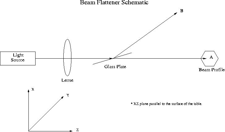
While trying to observe the reflection pattern on one of the glass cover plates we observed an interesting behavior. The plate that we used has a slight variation in its parallelity (arseconds range?) that makes it have a wedge geometry. We placed a 2cm focal length lense in the path of our laser and then we placed the plate perpendicular to the surface of the table tilted at some angle tiltednear the focal point. We observed the reflection at this point and we observed horizontal fringes that we attributed to the surfaces being not parallel (equal thickness wedge fringes). However, as we moved the plate along the propagation direction of the laser the horizontal fringes started to tilt until eventually at some point they were in the vertical direction (around half a meter away from the lense) . We didn't rotate the plate, it was only displaced along the beam. If these are wedge fringes, they should not change in direction. However, we observed the contrary and this have baffle us for the time being.
At the first we did not notice changes on the transmitted beam passing
through our glass platejust by observation.
However, when we used a beam profiler we could clearly see changes on the beam
profile intensity. These changes could be due to the wedge fringes and to the transmission
function. We tried to get rid of the wedge fringes by reducing the beam size on the surface
of the etalon until we could place the beam in a region between these wedge fringes. Once we
did this we observed in the beam profiler a flat region in the beam corresponding to one
of the higher order minima of the transmission function. However, this flat region
wasnt on the
*All the Mathematica files created by Joerg Bochman to which I added some
extra explanations for what the graph shows.
References
1. C. Xie, R. Gupta, and H. Metcalf, "Beam profile flattener for Gaussian beams",
Opt. Lett. 18, 173-175 (1993).
2. John A. Hoffnagle and C. Michael Jefferson, "Design and performance of a refractive
optical system that converts a Gaussian to a flattop beam," Appl. Opt. 39, 5488-5499 (2000).
3. Frank L. Pedrotti, Leno S. Pedrotti, Introduction to Optics, (Prentice Hall, New Jersey).
4. Melles Griot, Optics Guide 3, (1985).
| Stony Brook Laser Teaching Center | October-2003 |