Creating Airy Beams With
Simple Optical Elements
Jonathan Gill
mentors: Martin G. Cohen and John Noé
Laser Teaching Center
Department of Physics and Astronomy
Stony Brook University
Background
During the first couple of weeks of the 2014 LTC summer program I looked at many possible project ideas. One of these was related to creating Airy beams. These have very interesting properties, but the method I read about would have required programming a spatial light modulator (SLM). Coincidentally soon after this Dr. Noé came across a paper by Papazoglou et al (Phys. Rev. A, 2010) which described a much simpler method for creating Airy beams. I decided to try this idea out for my project, and we started that same day with some cylinder lenses that we found in the lab, a collimated laser light source, and the lab's beam-profiling camera. It took several refinements of this setup to get a good result, but after a couple of weeks I got very nice results that quite clearly demonstrate the fascinating properties of Airy beams.
Airy beams are optical wave fields with very unusual properties. Although they are called beams they are not contained within a limited cross-sectional area the way a typical laser beam would be. Instead they consist of an asymmtrical pattern of ripples, a primary or peak lobe with many increasingly smaller secondary lobes to one side. In a one-dimensional Airy beam there is just one such pattern of ripples, while in a 2D Airy beam there are ripple patterns in two orthogonal directions that share a single primary lobe. My experiments were with 1D Airy beams, which illustrate all the essential features of Airy beams.
Airy beams share many of the features of the better-known Bessel beams but also have two unique features. Bessel beams have a narrow primary lobe surrounded by circular rings of light, so they are inherently two-dimensional. On the other hand Airy beams can be either one- or two-dimensional. The narrow primary lobe or core in both Airy and Bessel beams maintains its width over a relatively long distance, so they are said to be non-diffracting. Both types of beams can also reconstruct themselves - if the primary lobe is blocked it will reappear on further propagation. The second unique feature of Airy beams, which is quite remarkable and also quite useful in certain applications, is that the lobe of highest intensity accelerates, that is, it propagates along a parabolic path.
 2D Airy beam, from physics.aps.org |
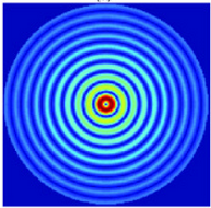 Bessel beam, from opticsinfobase.org |
Our results in this project so far very clearly illustrate the properties of a 1D Airy beam. In the future we hope to create Airy beams with mirrors rather than lenses, and to demonstrate the self-healing property. We also hope to model how the the aberrations of lenses or mirrors are used to create Airy beams.
History
The existence of Airy beams was first predicted by Michael Berry and Nandor Balazs in 1979. Berry and Balazs described a wave packet (a localized "burst") that does not spread and curves as it propogates from its origin. This Airy packet is made up of particles and has a probability distribution described by an Airy function which evolves according to Schrodinger's equation. They gave a quantum mechanical description of this wave packet using semi-classical orbits. However Airy beams were only created experimentally for the first time almost 30 years later, when Siviloglou et al [2,3] recognized that an Airy beam is the Fourier transform of a normal Gaussian laser beam with a cubic phase modulation. They used a spatial light modulator to create the cubic phase variation, and a lens to create the Fourier transform. Their results led to considerable popular interest in Airy beams and related phenomena. The method of Papazoglou et al [4] doesn't require specialized equipment and can be used with very high-powered lasers that would damage an SLM. Also, unlike a custom phase plate specifically designed to create a cubic phase modulation, it is tunable (adjustable). Since Papazoglou et al published their method, others have successfully used lenses to create Airy beam, including Yalizay et al, who used parts of two cylindrical lenses bonded together to create a single cubic element and Pacebal et al, who used a single cylindrical lens to generate Airy beams.
Theory
Aberrations
I began learning about aberrations using Wikipedia, Hyperphysics, telescope-optics.net, Principles of Optics by Born & Wolf, Basic Wavefront Aberration Theory for Optical Metrology, by James C. Wyant, and Useful Optics by Welford.
Comatic Aberration:

The image appears to have a "tail." This effect occurs when rays from
an off-axis image enter the lens or a curved mirror at an angle. Path length, or phase, of the light is different depending on its positionon the optic.
Thus the aberred wavefront is different from the original wavefront. The phase shift varies cubically with position in the optic (distance from its center).

Basic Setup
Our setup is based on that of Papazoglou et al illustrated in the figure below[4]. A relatively wide, collimated beam of light is incident on one side of two adjacent lenses of equal and opposite focal length. The tilt in the first lens creates the desired cubic phase modulation (coma). The second lens corrects for other aberrations and roughly collimates the beam. We used a single pair of cylindrical lenses one-dimensional in order to create w one-dimensional Airy beam. Not show in the diagram, a subsequent Fourier transform lens brings the beam into the far field. The focal length of this lens sets the scale of the final Airy beam.

For all of our experiments our light source was a Cambridge Collimators LM635 fiber-coupled diode laser, which produced a beam about 1.0 cm in diameter. The Airy beam images were observed and recorded with a Thorlabs DCC1545M CMOS camera, which was mounted on a rail. An ND 3.0 filter was mounted directly on the camera to attenuate the laser light to an appropriate level and suppress ambient light. The beam was about 1 cm in diameter. We aimed it on only one side of the lens in order to minimize certain aberrations.
Experimental Challenges
Lenses with Different Focal Lengths
At first, I used a -80mm cylindrical lens with a +100 mm cylindrical lens, since these were easy to find, and the difference in focal length made collimation painless. With this lens combination, however, the Airy beam was never quite right and spread out very quickly as it moved from the focal plane. Dr. Cohen suggested I either switch to two lenses of the same focal length or use a single lens as explained in this paper. I found a small, +80mm lense lying around on the optics table and used it. I have since generated much better Airy beams.
Space constraints
The difficulty with using two lenses of the same focal length is that one must closely space the lenses in order to collimate the light. In fact, if neither lens is tilted, then according to Gullstrand's equation there would have to be no space between the two. Tilting the negative cylindrical lens allows for spacing between the two lenses. Originally, with each lens in a clamp, I was unable to properly tilt and space the lenses properly. I had to remove the positive lens from the clamp and mount it on double-sided tape in order to allow for a greater range of motion. Camera Washing Out
Originally, I used a "naked" CMOS camera without a lens or filter. I set the pixel clock high
and the exposure time low, but the images I saw looked something like this:

At first I thought what I was seeing was the Airy beam. I was very confused when at the focal point the beam became a rectangular blob. Dr. Cohen pointed out that that the camera was actually getting overloaded with light. He suggested putting a neutral density filter over the camera. Currently, with an ND 3.0 the camera is no longer washing out and I am able to see the beam very clearly at the focal plane.
Final Experimenal Setup and Procedures
My final setup is shown in this picture. The lenses are -80 mm, +80 mm and +200 mm. The first two lenses are spaced approximately 2.5 cm apart with a tilt of 20 degrees for the negative lens. The separation varies based on the angle of the first lens. The camera records the beam at and near the focal length of the Fourier lens (20 cm).

Analysis and Results

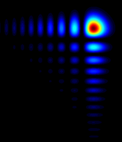
This animation shows a sequence of 16 images recorded in 5 mm steps over an 8 cm distance centered on
the image plane of the Fourier transform lens. The plots below show a slice through the image recorded
at the focal plane and a plot of the square of the Airy function. The results do not exactly match the
theoretical plot. This is partially due to ambient light, which prevents the intensity from nearing 0.


|
| This animation shows a sequence of 16 images recorded in 5 mm steps over an 8 cm distance centered on the image plane of the Fourier transform lens. The plots below show a slice through the image recorded at the focal plane and a plot of the square of the Airy function. The results do not exactly match the theoretical plot. This is partially due to ambient light, which prevents the intensity from nearing 0. |
On the right is a plot, created using ImageJ, of the intensity of the Airy beam at focus. The graph on the left is the square of an Airy function, the theoretical plot of an Airy function at focus.

The peak lobe of the generated Airy beam deflected parabolically in agreement with a theoretical trajectory. The slight discrepancy appears to be a linear component resulting from an angle between the path of the beam and the path of the camera.

The lobe width appears roughly constant within about 4 cm from the focal
plane. This shows the nonspreading property of the Airy beam. For
comparison, the divergence of a Gaussian beam with equal minimum width is
plotted as well.
Future Work
The next steps we may take with this project include creating Airy beams using mirrors in place of the lenses, demonstrating the reconstructing property of the beam by blocking a portion of the peak lobe, and verifying that the curvature of the beam is not affected by objects opposite the side of the secondary lobes.
References
- M. V. Berry and N. L. Balazs, "Nonspreading wave packets," Am. J. Phys. 4,
264-267 (1979).
The authors show that waves which are described by the Airy function propagate along a parabolic path and do not spread.
- G. A. Siviloglou, and D. N. Christodoulides, "Accelerating finite energy Airy beams," Optics Letters 32,979-981 (2007).
- G. A. Siviloglou, J. Broky, A. Dogariu, and D. N. Christodoulides, "Observation of Accelerating Airy beams," Phys. Rev. Letters 99,213901 (2007).
- D. G. Papazoglou, S. Suntsov, D. Abdollahpour, and S. Tzortzakis, "Tunable Intense Airy Beams and Tailored Femtosecond Laser Filaments," Phys. Rev. A 81, 061807(R) (2010).
- Yi Hu, Georgios A. Siviloglou, Peng Zhang, Nikolaos K. Efremidis, Demetrios N. Christodoulides, and Zhigang Chen, "Self-accelerating Airy Beams: Generation, Control, and Applications," Opt. Lett. 36, 3230 (2011).
- P. Acebal, L. Carretero, S. Blaya, and A. Murciano, "Generation of High-Quality Tunable One-Dimensional Airy Beams Using the Aberrations of a Single Lens," IEEE Photonics journal 4, 1273 - 1280 (2012).
- Pavel Polynkin, Miroslav Kolesik, Jerome V. Moloney1, Georgios A. Siviloglou, Demetrios N. Christodoulides, "Curved Plasma Channel Generation Using Ultraintense Airy Beams" Science 10, 229-232 (2009).
- Daniel M. Greenberger, "Comment on 'Nonspreading wave packets,'" AJP 48, 256 (1980).
- Berna Yalizay, Burak Soylu, and Selcuk Akturk1, "Optical element for generation of accelerating Airy beams," J. Opt. Soc. Am. A 27, pp. 2344-2346 (2010).
The authors investigate the possibility of generating finite Airy beams.
Details the creation of optical Airy beams using an SLM-generated phase mask and a Fourier transform lens.
Explains how Airy beams were generated with cylindrical lenses.
A useful reference describing current methods of generation and applications of Airy beams.
Authors used a single lens to generate an Airy beam.
Among other things, the authors derive the equation which can be used to calculate the acceleration of an Air beam based on the FWHM of the peak lobe at the focal plane.
Greenberger offers another explanation of the Airy packet using the equivalence of gravitational and inertial mass.
Parts of a positive and a negative cylindrical lens are cut and glued together to create a cubic element. The element is used to generate Airy beams.