Certain materials respond well to irradiation from different sources. "Glow-in-the-dark" materials, for example, respond to irradiation from visible light by emitting their own visible light. This is an example of luminescence.
Another example of luminescence is that which is induced by some radiation other than visible light. Some solids, for example absorb x-rays, gamma rays, or beta radiation and acquire defects in their lattices as a result. These defects, which are charged, then act as "color centers," that is, they will emit a certain color of light when a different light is shone upon them. In Al2O3, the crystal absorbs light of 532 nm (green) and emits light at about 410 nm (blue). (This is not to say that some of the green light does not get transmitted.)
By inducing luminescence by heat (thermoluminescence/TL) or visible light (optically- stimulated luminescence/OSL), it is possible to tell how long a rock or work of pottery has been buried. This has recently been used in dating several ancient pieces of pottery.
It is often necessary to determine the dose of radiation that someone has been exposed to because of the conditions in which he/she works. In this instance, the defects in the crystals are created and then "read-out" by OSL.
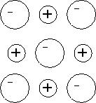
| The simplest example is NaCl. A pure sample of NaCl will look like this (right). Here, the lattice takes on a regular, repeating shape. |
|
|
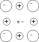
After irradiation with x-rays, gamma rays, or beta radiation, the resulting crystal will look like this (left). Some of the anions have fallen out of the lattice, and single electrons have taken their place. These "holes" are called F-Centers. |
In Al2O3:C, the carbon-doping serves to create the defects. The irradiation, then locks electrons into the defects. When the electrons are induced to leave the lattice, there is an emission of luminescent light. Due to the fact that the anions have two different oxidation states in aluminum oxide, the defects can either be F- or F+-centers.
The sample is irradiated with x-rays at 25 kV and 100 microamps for one hour. The crystal is then tested for OSL. (This is a test condition; one of the experiments will be to vary the current and see its effect on the OSL.)
The photodiode is connected as follows:
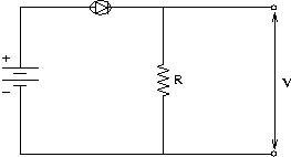 |
V = Potential Difference R = Resistor of Arbitrary Resistance |
By applying Kirchoff's Loop Rule, it is found that: V = IR because the potential drop across the resistor must be equal to the potential gain across the source of potential which is proportional to the induced photocurrent (I). At the terminals, a voltmeter or oscilloscope is connected.
It, here, becomes apparent that the resistor will determine the potential and, hence, the precision of the measurements.
By placing a blue filter immediately between the crystal and photodiode, the 532 nm light from the laser will no longer be visible. The 410 nm band is then expected to emerge from the other side. This corresponds to F+-center emission.
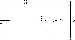
| The above model is actually slightly idealized. The problem is that the coaxial cable actually has some capacitance, C. As a result, the circuit acts as an RC circuit, constantly charging and discharging. |
|
As the cable charges, governed by the equation
 (where
  =emf=V),
the potential changes. After the potential exceeds a certain threshold value, the
cable discharges and then proceeds to recharge. This causes a new oscillation in the
wires, causing the oscilloscope to pick-up this wave. This makes the precision of the
oscilloscope irrelevant because at higher precision, it is an inaccurate read of the
photodiode.
=emf=V),
the potential changes. After the potential exceeds a certain threshold value, the
cable discharges and then proceeds to recharge. This causes a new oscillation in the
wires, causing the oscilloscope to pick-up this wave. This makes the precision of the
oscilloscope irrelevant because at higher precision, it is an inaccurate read of the
photodiode.