|
Weekly Progress Report
February 12, 2001
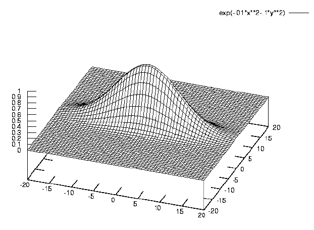
A diode laser came with the hologram kit. Without its collimating lens,
it diverges naturally, which makes it good for holography. I'm spending
this week mostly playing around with my laser, checking its divergence and
so forth. Its intensity profile appears Gaussian in both the vertical and
horizontal axes. After plugging a few numbers, I have found that this
particular laser diverges 13.24 degrees in the horizontal direction, and
4.03 degrees in the vertical.
pics: 1,
2,
X & Y graph of intensity profile
February 19, 2001
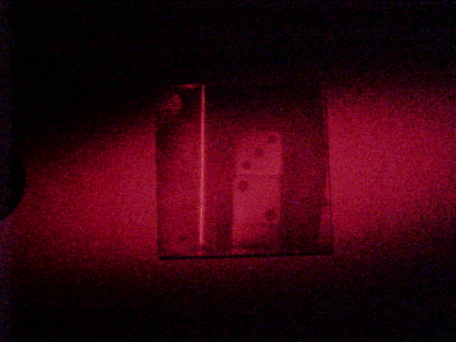
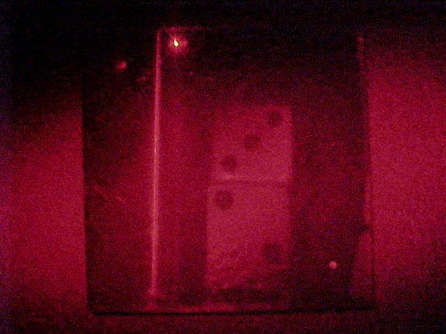
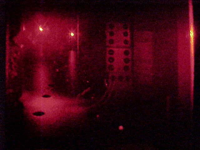
This week I made my first successful hologram. The entire image was
supposed to be of two dice and a mini lighter, but it came out
underexposed so only one of the dice can be seen clearly. I could tell it
was underexposed because the brighter portion of the beam was directed
onto the visible die and it received the most light. Next I'll try to
double the exposure time from 60s to 120s.
February 27, 2001
So far this week I have made two holograms (today) and I am waiting for
them to dry. As I was exposing the plate, I noticed a ring-like pattern
being reflected back in my direction. I found out later that this was an
interference pattern
caused by two beams of light that were reflected off
of both the front and back of the plate. It looked much like the "bulls
eye" pattern created by a Michelson interferometer, but much more stable
and circular.
March 8, 2001
Only one of the two previous holograms came out and only a bit of it was
visible. A lot of the evidence is now pointing to overexposure as a cause
of this problem. In an attempt to get to the bottom of this, I took one
plate and overexposed half of it while covering the other side. This will
give me a good idea of what to look for in the holograms I have already
attempted. Although the plate is still drying, the overexposed half
seems to resemble the plates with nothing on them more than the
underexposed half. This is a good thing because it backs up the idea that
I have been overexposing these plates all this time.
March 13, 2001
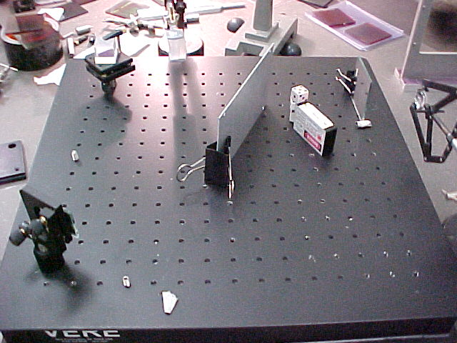
Today I have changed my setup a little. I have kept my usual dice and 60
second exposure time, but I have increased the distance between the laser
and the plate to 40 cm as it is suggested in a booklet that came
with the kit. Doing this will not only decrease the overall intensity
of the light, but it will also make the total distribution of light more
even over the entire plate. This is good not only because I need less
light, but because every object behind the plate will get the same amount
of light.
March 28, 2001
My latest hologram is the best yet. Using the new setup I was able to
create a pretty clear image of a post that was screwed into the breadboard
and three dice. The first time I tried this it didn't work because
the plate was placed in the developing tray face down and wasn't exposed
to enough developer. Before I attempt making a transmission hologram I
intend to make two more reflection holograms, one of posts at different
distances, and one of a mirror, just to see what happens.
April 5, 2001
So far I have found that an object distance of 40 cm and an exposure
time of 60 seconds to be best for the particular plates and laser that
I have been working with. Time hasn't allowed for further experimentation
with transmission holograms, but hopefully I can continue work with them
next semester. I also would like to find a way of calculating a proper
distance and time with the use of the plate and laser
specifications, this will help save time and materials in future
experimentation.
June 21, 2001
I am now working under the REU program and continuing my work with
holograms. This time I plan to study them with more of an emphasis on
applications. For the past week or so I have been reading up on
holographic applications and making a few transmission holograms and
another reflection hologram. Upon viewing my reflection holograms
with the diode laser I found that not only are they much clearer than
I had previously thought, but there are also other images (both
reflection & transmission) hidden there as well. So I have actually
made a few transmission holograms without actually realizing it. In
just about every hologram I have made, there is an unintentional
reflection image of the clip used to hold the plate and a transmission
image of the optical board used to keep everything stable. The one
transmission hologram that I made intentionally was fairly successful;
it consisted of a chunk of styrofoam, a keychain, and three mirrored
balls taped together. The mirrored balls were visible, but not great,
the styrofoam was barely there, and the keychain came out fine. I've
found this to be true regardless of the type of hologram: highly
reflective objects (ie. mirrors and silver balls) are difficult, but
not impossible to capture, and Styrofoam and paper barely create an
image at all. I believe that this is because objects that have too
high of a reflectivity cause overexposure, and the softer objects do
not create a solid enough wave front to interfere properly.
June 24, 2001
I just found out that until recently, images of people have not been
too popular in the field of display holography. This is due to the
fact that the red light emitted by the ruby pulse laser (commonly used
to create images of non-stationary subjects) easily passes through the
water based tissue of human flesh. This can be observed when holding
a red laser up to one's hand and noticing that the light passes
through while the light of a green laser does not. I tried this
little visual test with the styrofoam and the light passed right
through, even more so than for my hand. So I was correct in assuming
that the styrofoam could not create wavefront uniform enough for
interference, but I was wrong in assuming that this was due to its
texture. -- Michael Polyakov, a local high school student, has done
work with photon migration in human tissue, this is his webpage
June 29, 2001
The few transmission holograms I have attempted thus far have been
pretty successful. The most difficult part is deciding where
everything goes in the setup: it's hard to know whether everything is
getting enough light or not. This and other more spatial problems
will not be as much of a consideration if I decide to use a multiple
beam setup. One thing that I don't like about my transmission
holograms is that you need to have the room lights off to view them.
This weak image is either a property of the type of plate I'm using
or I'm exposing improperly. Aside from the transmission holograms I
have also made a hologram of my original "dice and post" hologram that
at times seems even clearer than the original. I have also tried
making a diffraction grating using the setup suggested in a book that
came with the kit. It diffracts a little, but not as much as I would
have liked. One strange thing about the diffraction grating is that
the lines seem to be perpendicular to the direction I expected them to
be.
pics: original hologram & copy
July 6, 2001
In my first attempt to create an interferometric hologram, I atatched
a micrometer to the breadboard and checked for stability. I used a
mirror as an optical lever and discovered that the bubble wrap alone
is better for stability than the large packaging bubbles I have been
using recently. I then screwed a few posts into the micrometer and a
few into the breadboard so there would be fringes on some and not on
others. The hologram was exposed for 30 seconds and then for another
30 seconds after a slight adjustment on the micrometer. Because the
markings on the micrometer are hard to see in the dark, I turned it
all the way in one direction until it wouldn't go any further and then
turned it back one mark (25 microns). This way when I was in the dark
and wanted to move the micrometer, all I needed to do was turn it
until it stopped. At first I didn't see any fringes and I thought
something might be wrong with my setup or the distance I moved the
micrometer but later I noticed a few vertical fringes on a white tag
on the micrometer. I believe that these fringes are not visible on
the posts because the posts themselves are vertical so their image may
be between the fringes (if this is possible). Other fringes that I
have noticed in my transmission holograms thus far have been of a
different nature, they cover the entire image and look more like bars,
or pond ripples that float front of the object. The fringes that I
made intentionally were more solid and behaved as if they were glued
to the object images, these are the type of fringes that I have read
about and expected.
July 17, 2001
I ran out of plates about a week ago and the new batch just arrived
yesterday, I made a reflection hologram of my keychain and a die (I
can't get enough of the dice) just to test the plates. The image is
slightly blurred, and has interferometric fringes on it. At first I
believed this was due to a slight movement of the plate during
exposure until I noticed that there were no fringes on the die. When
I viewed it with the laser many more of its charateristics became
visible. The entire image became extremely clear, which was not as
much of a s urprise to me because I've viewed other reflection
holograms with a laser and seen this before. With the laser light and
just the right angle I was able to see the imaage of the roll of black
duct tape that I used to support the keychain. I was expecting to see
fringes on it as well because I believed that the fringes on the
keychain were due to the tape sliding a bit but there were no fringes
on the tape so the keys must have moved by themselves. This is
reasonable because they were leaning on the tape roll and weren't
quite as sturdy as they could have been.
July 23, 2001
last week I made a hologram with the 5 mw HeNe laser used in the fiber
optics setup. Its probably the clearest hologram I've made yet. I
attempted two more after that (one of a baseball and one of a pocket
watch) with limited success. The fact that I can make good clear
holograms with it is a good thing though because now I know that if I
can get the exposure time right, I will be able to make much quicker
exposures with the 7 mw HeNe. Experimenting with the 5 mw HeNe was
worth while because it had the intensity distribution of the more
powerful laser with the same output power of the diode laser I have
been using up until now.
I've just been told that the HeNe
that I made the exposure with is only a 1 mw laser so today I plan to
use a photocell and measure its output power and make sure.
July 25, 2001
After examining the lasers with a photocell and voltmeter I found that
the HeNe has a power of .69 mw and the diode laser emits about 2.63
mw. Both of these numbers are less than I had expected. I set up the
breadboard to record a double beam transmission hologram today and
exposed the same setup twice; one for 45 seconds and another for 130.
Surprisingly, both holograms created comparable images, but the 45
second setup is slightly brighter. In both cases the object is too
far away from the plate so before I leave today I'll make another with
the object closer to the plate.
July 31, 2001
Yesterday I made two holograms with the black HeNe (7.5 mw). The
exposure time was about 6 seconds. Neither of the images were very
successful. I'm guessing that this is due to the relative
intensities of the reference beam and the object beam. If one of
these is too strong, it might cause the interference pattern to fade,
causing the image to fade as well. If this is true, it may explain
why I was able to record the same hologram with two drastically
different exposure times; if the intensities of my object and
reference beam were matched perfectly, they would completely cancel
each other out in some places, making an exact exposure time less
important.
August 17, 2001
To study the effects of different intensities with respect to my
object and reference beams I have begun a study of the beam splitter I
have been working with recently. I was curious how the incident angle
affected the intensities of the two beams. So far I have collected
data for the transmitted beam passing through both sides of the
reflecting surface and they are virtually the same. Both sides
transmit about 50% of the light at 45 degrees but behave strangely at
different angles. I'll post my data as soon as I can.
August 31, 2001
The reason I have become interested in the intensities of the separate
beams is that the quality of my transmission holograms. Whenever I
make one, I'll get an image of the object I want, but mostly of the
side of it where the edge of the reference beam hits it. I usually
see none of the side of the object I intended on making an image of.
Today I exposed two transmission holograms, one with the reference
beam 10 times the intensity of the object beam, and one opposite.
Both had little to no image to playback. The one transmission image
that I have successfully made of the front of an object is still a
mystery to me, possibly because I blocked the reference light from
behind the object. I'll try doing that again next and see if it
works.
September 4, 2001
After learning more about the zone plate description of transmission
holograms, I could explain a phenomenon that I had noticed a while ago
and couldn't account for. When I shine a laser beam through a
transmission hologram at a certain distance from the wall, I can see a
real image projected on the wall. It turns out that a zone plate
diffracts light in such a way that it creates two images, one real and
one virtual. The virtual one is the one that you are used to seeing
when you look into a transmission hologram, and the real one is the
one you can project onto a wall, much as you would with a lens. In an
attempt to view this same real image with a wider beam I telescoped my
diode laser's beam as best I could and shined it through the hologram.
Although I didn't see an image of the dice, I saw something else that
was much more peculiar: off to the side there was a square of light
that behaved exactly as if it were being projected through the
hologram as a window, I saw no dice, but "shadows" of two of the
objects in the scene. The strangest thing about this image is that it
can be focused into a point and inverted by changing the distance
between the hologram and the wall.
September 6, 2001
Trying to get to the bottom of what was wrong with my setup, I made a
transmission hologram with the same setup used to make the working
hologram. The setup is pretty much the same as usual but blocking the
reference beam from in any way hitting the object (especially on the
side) and it was successful. The image is of three dice and a diode
laser box. Its pretty clear but cuts off sharply half way past the
box. After examining my setup, I noticed
that a bit of the reference beam bounces off of the plate and onto the
objects in the same places the image was visible. This lead me to
believe that it was the reference beam and only the reference beam
creating the image. To test this I made an exposure for the same time
(60s) but this time without the object beam. It made virtually the
same hologram. What's weird about
this is that the light bouncing off of the plate and onto the object
is so faint compared to the object beam that you can't even tell
whether its there or not, and yet its the only light bouncing off of
the object that creates an image. This tells me why I've only been
seeing the sides of most of my objects, but I still don't know why the
"real" object beam isn't doing its job.
October 1, 2001
Another problem that arises often making holograms is the beam
profile. In many lasers (like the white HeNe I'm using now) the beam
isn't so clean for one reason or another. It was pointed out to me
that a single mode fiber optic cable produces a perfect gaussian beam.
Because the cable does not preserve polarization, I assumed that the
coherence of the light would be lost upon passing through the cable
as well. To test this I built a little Michelson interferometer on my
breadboard so that a divergent light could be passed through it
causing an interference pattern. I knew it worked because I held my
diode laser up to it and observed fringes on the wall. When I
stretched the cable across the room and send its light through the
interferometer I saw the same thing.. fringes. Since then I have made
a pretty high definition hologram with the cable, proving that the
light is indeed coherent and effective for making holograms.
October 2, 2001
I've been
looking at the diffraction caused by the pattern created on many of my
transmission (and a few reflection) holograms, trying to figure it
out. At first I believed that it was just the holographic pattern
diffracting the light, but this diffraction is much too grating like
to be the holographic pattern. One thing I've noticed is that it only
takes one beam to make, so it must be either the light bouncing off of
the breadboard, or the light bouncing off of the back of the plate
causing the pattern. I exposed two plates today, one with the light
shining directly in, and one with the light shining in at 45 degrees.
I planned on seeing a large interference pattern on the first, which I
did, and a grating like pattern on the second. The pattern on the
second wasn't there and I'm assuming that this is either due to the
resolution of the emulsion, or that the cause of the pattern is
something else.
October 22, 2001
I just came back from the annual meeting of the OSA (Optical Society of
America) in Long Beach, California, where I gave a presentation on my
work in holography for the symposium for undergraduate research and
attended talks on various topics involving optics. My talk consisted
of both recent work and things I did almost a year ago. Although
what I've done seemed a bit simplistic in comparison to some of the
other students' projects, it was still fun to talk about something I
knew, especially when others showed interest. I was only asked a few
questions, mostly about my diode laser and why I used it. I attended
as many talks as I could while I was there, mostly those dealing with
atomic physics, and a few on quantum phenomena and their applications.
I was especially interested in evaporative cooling,entangled states,
and just about anything that dealt with manipulation of atoms and
atomic beams. One talk in particular that caught my eye involved
guiding atoms through a fiber optic cable. Although much of it went
over my head it was great to be there and see what's going on in
optics today and to get a feel for what life might be like after
school. It definitely gave me a good reason to pay attention in class
too, I saw a few examples of applications of things that I've already
learned. Its nice to know that this stuff can and IS actually used in
the real world, and isn't just something you're required to learn for
a degree.
March 21, 2002
Since the OSA meeting I have been fairly busy. One thing that has
spiked my interest recently is interferometry (with non laser sources
in particular). I have built both Mach Zender and Michelson
interferometers in the hopes of observing fringes from a Sodium Vapor
lamp with no success so far. Possible reasons for this are the source
and/or the coherence length of the light. To create my source, I
first blocked most of it with a piece of cardboard, the rest passed
through a pinhole and was collimated with a lens. I noticed that the
light passing through one of the arms was significantly brighter than
the other, I'm assuming that this is because the beam spliters don't
split the yellow sodium beam in two as perfectly as it does with red
light. Allthough this is a problem, I'm pretty sure its not whats
causing the lack of fringes, it would just make them harder to see.
June 25, 2002
I've been working in the Laser Teachng Center this summer helping to
work out the bugs in a laboratory session for the new optics course
that will be offered in the fall. So far the plates have not arrived
and I have been keeping myself busy with other things. Brendan Wyker,
a visiting REU student from Misouri, has done previous work with
sodium and has observed the doublet with a Michaelson interferometer.
We recently receieved a number of optical devices that were donated
from the hospital, one of which was a finely tuned spectrometer.
Because I didn't know what it was, I took it apart to play with its
components (a difraction grating in particular) and have since been
charged with re-alligning it. We got it to work yesterday and we
observed both the sodium doublet and my diode laser operating in
several modes. It was interesting seeing it switch through modes
while heating up and I'm excited to look at other sources.
June 26, 2002
Today I hooked up a diode laser to a variale voltage source and shined
it into the spectrometer. It was pretty difficult focusing the beam
tightly and it was so bright that I needed to use a filter on top of
the polarizer to attenuate it. Looking at the setup at the end of the
day I've realized that part of the problem may be that some of its
components are raised to different heights than others, so tomorow I'm
going to re allign everything and make sure each beam path is level.
So far I've learned that the scope tends to produce a lot of
background noise when first plugged in, and that the ratio of the
sodium doublet intensities varies as the lamp heats up.
July 5, 2002
The plates and developing chemicals came a few days ago. Today I
mixed the chemicals and I am preparing to make my first hologram. My
setup has a set of keys with two dice resting on top. The concave
lens used to expand the beam is about 50 cm away from the plate. In
an attempt to make a diffraction grating I shined the same beam onto a
pair of mirors and back towards the lens at slightly different angles,
I placed the plate in their mutual path in hopes of recording the
interference. So far it doesn't seem as if either has been
sucessful, but they haven't dried yet.
July 8, 2002
Out of the two holograms I processed on friday, the only noticable
change in one of the plates is that when a laser beam is shone through
it, it creates a ring of light around it. This is something I haven't
seen before in a reflection hologram (or a transmission hologram for
that matter). I only thought to shine a beam of light through it
because when I held it up to my eye, I could see a rainbow colored
ring around point sources of white light. I believe that the pattern
creating this diffraction consists of small spots rather than grating
like lines because it diffracts in all directions, not just two. I
exposed and developed two more reflecion holograms today, with five
second exposures each (this time with a safety light in the developing
room). The reading material that came with the developing chemicals
said that the developer should make an exposed plate black (letting
about 1% of light through) Allthough its hard to tell how much is
getting through, it looks like more than 1% is transmitting so maybe
my plates are underexposed.
July 9, 2002
Today after exposing two holograms for 7 and 9 seconds with marginal
results, I took a reading of the intensity of the diode beam at 40 cm
from the laser and estimated an exposure time of about 4.5 seconds
based on the film sensitivity. Using aproximately this time I exposed
two plates and am now waiting for them to dry.
Sept 10, 2002
I've found that an exposure time of about 7 seconds works best with
the laser diode at 40 cm. To see how well the new plates work with
HeNe light, I expanded a HeNe beam over about 2 m so it covered the
whole plate. Measuring the peak intensities of both the HeNe spot (at
2m) and the diode spot at 40cm, I found that the diode's peak
intensity is twice that of the HeNe's, so I exposed two holograms for
about 14 seconds. Both came out as good as any of the holograms I
have made with the diode. How visible the image is has a lot to do
with the sourse used to view it and what is behind it. Light from a
flashlight, laser light, and sunlight are all good for viewing
holograms but the images can't be seen unless the hologram is placed
over something dark. The reason for this is simply that only a small
fraction of the incoming light is used to produce the holographic
image. If any significant ammount of light passes through to your eye
from the behind the plate, it completely washes out the image because
it is much brighter.
Sept 10, 2002
A while back (I'm not sure if I commented on this before) I made a
fairly succesful transmission hologram by accidentally using the light
that bounced off of the plate as an object beam. In the hopes that
the small amount of light reflected from a glass surface could act not
only as a suitable object beam, but a reference beam as well, I placed
a glass plate about 8cm away from the object, directly in the beam
path and stole a little bit of this beam for the reference. Exposing
one for 14s and one for 30s with the HeNe as before, I was surprised
to find that each produced a fairly bright image, allthough a bit
fuzzier in the 30 second case. The advantage of this setup is that
there are only two optical elements between the laser and the plate
(lens and glass plate). This lack of mirrors beam splitters and
additional lenses provides for a very clean wavefront.
Sept 30, 2002
Today I exposed four transmission holograms with only the glass plate and the expanding lens. Two of them use the direct laser beam as an object beam and the other two use it as a reference beam. one of the later holograms is of a bicylce chain and both the holographic plate and the beam spliting plate reflect light onto it. The diference can be seen (if the image is visible) by the spacing between fringes. The splitting plate's object beam is reflected at a sharper angle, causing the fringes to be closer together.
Oct 23, 2002
I exposed to reflection holograms today, both with the instructinal lab's diverging lens. at ~3 meters away with the HeNe I exposed for 7 seconds and at 2 meters away with a .75 mw diode laser I exposed for 10 seconds.
Nov 1, 2002
After seeing promising results with the HeNe at 3m, I've decided to try exposing at 4m to get a more even distribution of light over the plate. I exposed two reflection holograms with exposure times of 12 seconds and 17 seconds. These times were decided upon from two seperate estimations of the intensity of the light at 4m: calculation, and measurement, respectively. I made a scratch in the emulsion of the plate with the smaller exposure time which has become my convention.
|