October 23, 2000
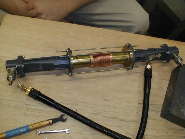
This week I took more measurements with a cavity consisting of one bellows. The piece that we are making to allow two cavities to be directly coupled was not ready yet. At the recommendation of Dr. Koch, I measured the transmitted power through the filter system without the bellows in the middle. In this setup the pipes seen in the picture are butted up directly against each other. The plot shows the transmitted power with and without the bellows for comparison (input power is -10 dB). This shows that most of the attenuation is coming from some other part of the setup. The bellows does seem to cause a dip between 9 and 10 GHz. I would like to measure the shift in a resonance of the direct couple cavity with changing length before presentation on Wednesday.
October 16, 2000
The problem of the bellows bending when compressed was fixed by placing an extra set of nuts on each threaded rod to prevent motion of setup along the rod in both directions. Now with the proper adjustments to the screws, the bellows can be set to a specific length without bending. I also did some preliminary measurements to look at the transmission through the bellows with the irises in place. First I measured the transmitted power for different lengths and then repeated the measurement for irises irises with different hole diameters. Next we plan to put the other bellow in the setup to make the direct coupled cavities. To do this we must figure out a way to connect the two bellows with an iris in between them.
October 9, 2000
This week I placed the bellows inside of the filter assembly with no irises to check the transmission. The S21 measurement for transmission through the bellows was around -20 dB for the frequency range that the filter will be used. This means that the bellows does not make a very good waveguide. I am trying to find a better way to place the bellows in the filter setup without bending them when they are compressed.
October 2, 2000
This week I measured the S21 parameter (Span 7 GHz and Span 2 GHz) for one of the filters for which the idea of the tunable filter is based. The filter is designed to pass frequencies around 10 GHz for the parameters chosen. I also started taking measurements to determine the impedance of that filter. I am in the process calculating how the ridges in the bellows will change the resonances of the cavity.
September 25, 2000
This week I studied the TE and TM modes of a cylindrical cavities. I started by calculating the frequencies of the different modes of an ideal cylindrical cavity of the measured dimensions. Then I used the vector network analyzer to measure the resonances of the different modes. I verified that they were the correct modes by inserting metal into the cavity to perturb the resonaces. The direction of the frequency shifts provided information about what type of mode and the number of nodes.
September 18, 2000
I started by reading an article titled Direct-coupled-cavity bandpass
filters using scrounged rectangular-to-circular waveguide transitions by
S.A. Zelanzy and P.M. Koch. It describes how to make a microwave
bandpass filter that can be modified for different frequencies.
This design will be the basis for the variable frequency bandpass filter
that we are going to build. For background information on microwave
cavities and waveguides, I looked in a number of sources including;
Classical Electrodynamics by Jackson, Microwave Devices and circuits by
S. Y. Liao and Chapters 23 and 24 of Volume 2 in the Feynman Lectures on
Physics. I also started to learn how to use a vector network analyzer.
Here is a S21 measurement made on a 10.24 GHz
bandpass filter that is used as a test device for tutorials.