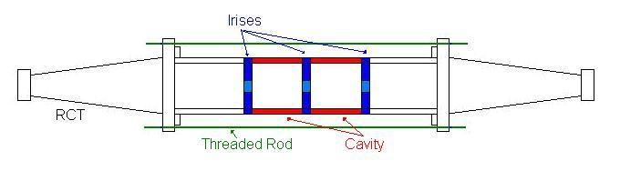
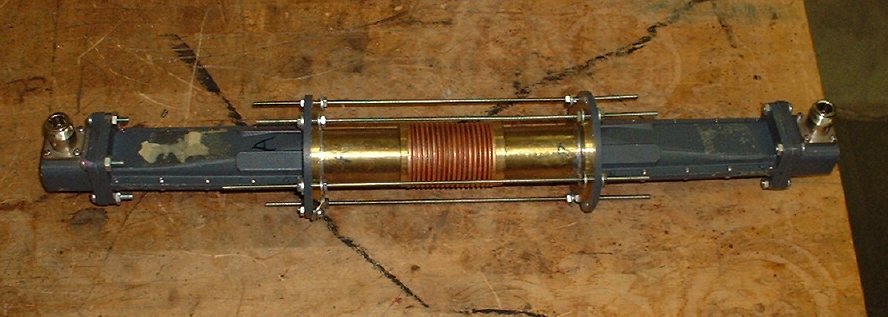
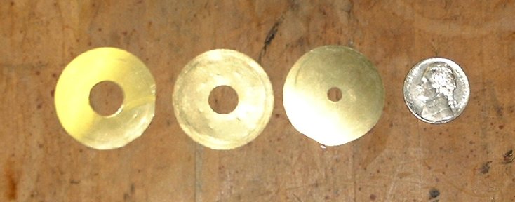
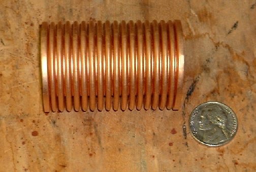
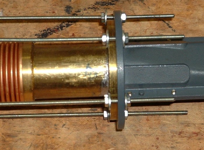
The filter setup in the article is shown in the diagram above. The ends are rectangular-to-circular transitions from a HP series 382A variable attenuator. They allow a transitions from rectangular waveguide commonly used, to the circular waveguide that makes up the filter. Then brass tubes act as a circular wave guide and are attached to the transitions. In the middle are two more pieces of circular wave guide that make up the cavities used as the filter. Irises made of brass shimstock with holes drilled in the center are placed at the ends of the cavities and between the cavities. Once the pieces are aligned they are held in place by threaded rods that pass though the rectangular-to-circular transitions. To change the frequency of the filter the nuts on the threaded rods are loosened, the cavities are taken out, and new ones at the desired length are inserted in their place. Every time a new frequency is desired, new tubes of the required length must be machined. The proposed design replaces the tubes with bellows of variable length. To change the frequency all that would be required is a compression or relaxation of the bellows and a readjustment of the nuts. In order to accommodate the bellows, collars were expoxed to the waveguides so that the ends of the bellows fit snugly over the collars. At his point we have only had one of the bellows in the filter setup. We did not have time insert both bellows into the setup in the time allotted for the rotation. The irises are placed between the bellows in the same manner as before. The bellows are much more flexible then the brass tubes and have a tendency to twist and bend under its own weight. An extra set of nuts was placed inside the holes to restrict the motion in both directions along the rod. This stops the setup from twisting and bending, but at least ten nuts have to be moved to change the length of the bellows.