Identifying the Topological Charge of Optical Vortices Through Diffraction
David Meltzer, Stony Brook University
Marty Cohen and John Noé, Laser Teaching Center, Stony Brook University
Introduction
In this experiment I attempted to measure the topological charge of a Laguerre Gaussian mode by using its diffractive properties. Working with an open cavity HeNe laser, I produced HG modes by introducing a hair into the cavity. I then converted the HG modes into LG modes using an astigmatic mode converter that exploits the Gouy phase[1]. With different apertures I then tried to see how the topological charge affected the diffraction pattern and what information the pattern could give about the topological charge.
This experiment was inspired by the work done by J.M. Hickmann, E.J.S. Fonseca, W.C. Soares, and S.Chaves-Cerda with vortices and a triangular aperture. They showed that if a vortex beam is shined on a triangular aperture the resulting far field diffraction pattern gives a very simple and elegant way of measuring both the sign and absolute value of the topological charge. The number of the points on a given side of the triangle equals the topological charge plus 1 (e.g. a triangle with 5 points on a side means the beam has TC=4) and the orientation of the triangle depends on the charge [2].
Background
It has been well known since the 1930s that light can carry spin angular momentum in the form of circular polarization. This is analagous to the momentum carried by a planet as it spins about its axis. However, it wasn't until 1992 that physicists discovered that light can also carry orbital angular momentum (OAM) [5]. This is similar to the momentum carried by a planet as it goes around a star.
More specifically, in 1992, it was found that Laguerre Guassian (LG) modes are the beams that carry OAM (they are not unique in this though). Laguerre Gaussian beams are a kind of transverse (spatial) mode that are solutions to the paraxial wave equation, along with the regular gaussian mode and Hermite-Gaussian (HG) modes.
Regular Wave Equation: 
Paraxial Wave Equation: 
The intensity patterns for an HG mode has rectangular symmetries while the LG mode has cylindrical symmetries. HG and LG modes each form a complete basis for all laser modes, ie any laser can be described as a superposition of either.
The relevant equations are:
Gaussian beam


 (Rayleigh range)


Here w0 is the beam waist and we choose the z axis such that z=0 at the beam waist, R is the curvature of the beam, and the rayleigh range is the distance from the beam waist to where the area of the beam doubles. The last term gives the equation for the Gouy phase, a crucial term for converting an HG mode into an LG mode.[6]
Hermite Gaussian beam
 [7]
[7]
 [8]
[8]
The second equation gives the formula for the Hermite polynomials.
Laguerre Gaussian beam
 [6]
[6]
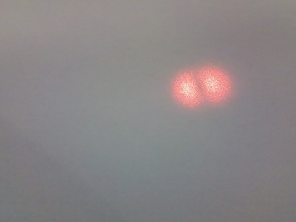
Here the C term in the first equation is a normalization constant and the second equation gives the equation for the genaralized Laguerre polynomials. The important term in the first equation is the exp(i*l*Φ) term. It is this term that gives certain LG beams their vortex properties. The azimuthal angle is undefined at the center of the beam, so that is a singularity of the electric field and a point of zero intensity. The topological charge, l, give information on how much the light beam "winds", ie how many phase shifts of 2*π occur in one wavelength. The orbital angular momentum of the beam is proportional to the topological charge (TC) and equals l*ℏ per photon[9].

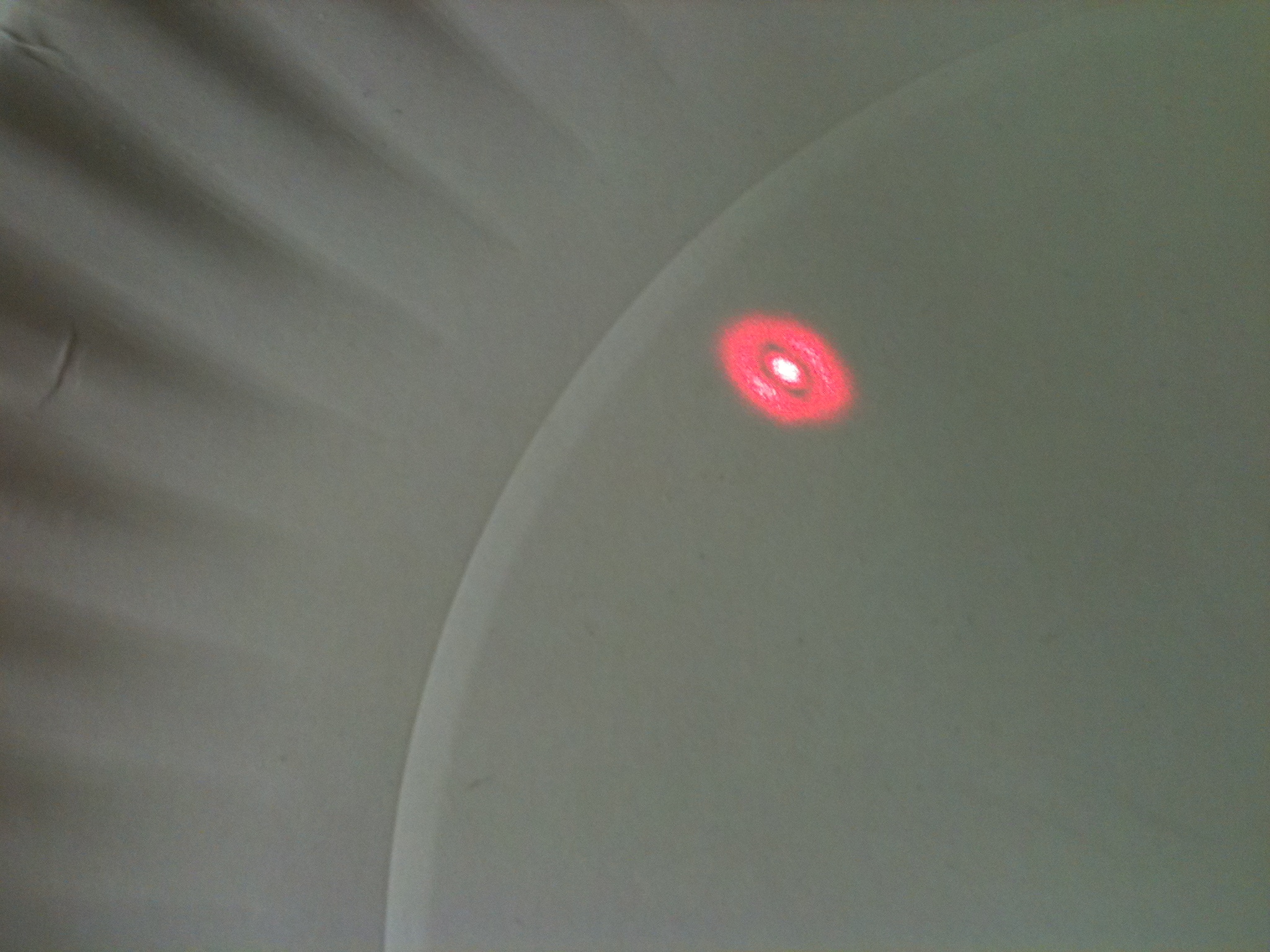
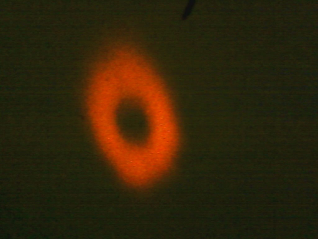
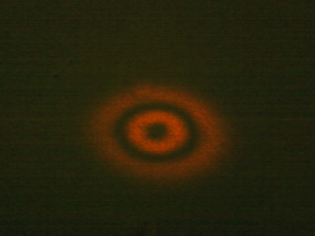
(a) shows a vertically polarized beam with TC=0 and the (b) shows a vertically polarized beam with l=1.

Laser Mode Conversion
 [11]
[11]
This open cavity laser usually produces a multimode beam, ie a superposition of many different modes, and by introducing a hair into the laser cavity I was able to select certain HG modes. Using an astigmatic mode converter, which consists of two cylindrical lenses of the same focal length a distance √2*f apart and rotated 45° with respect to the incoming HG mode. It is also required that the beam's waist falls in the center of the two cylinder mode converter and that the Rayleigh range of the incoming beam equals (1+(2)^(-1/2))*f. Here f denotes the focal lengths of the two cylindrical lenses.

This mode converter exploits the Gouy phase and introduces a π/2 phase shift between the two HG modes in the decomposition by changing the Rayleigh range of only one of those HG modes. When the beam goes through the second lens the astigmatism is removed and the two beams match up again to produce a LG beam. [1]
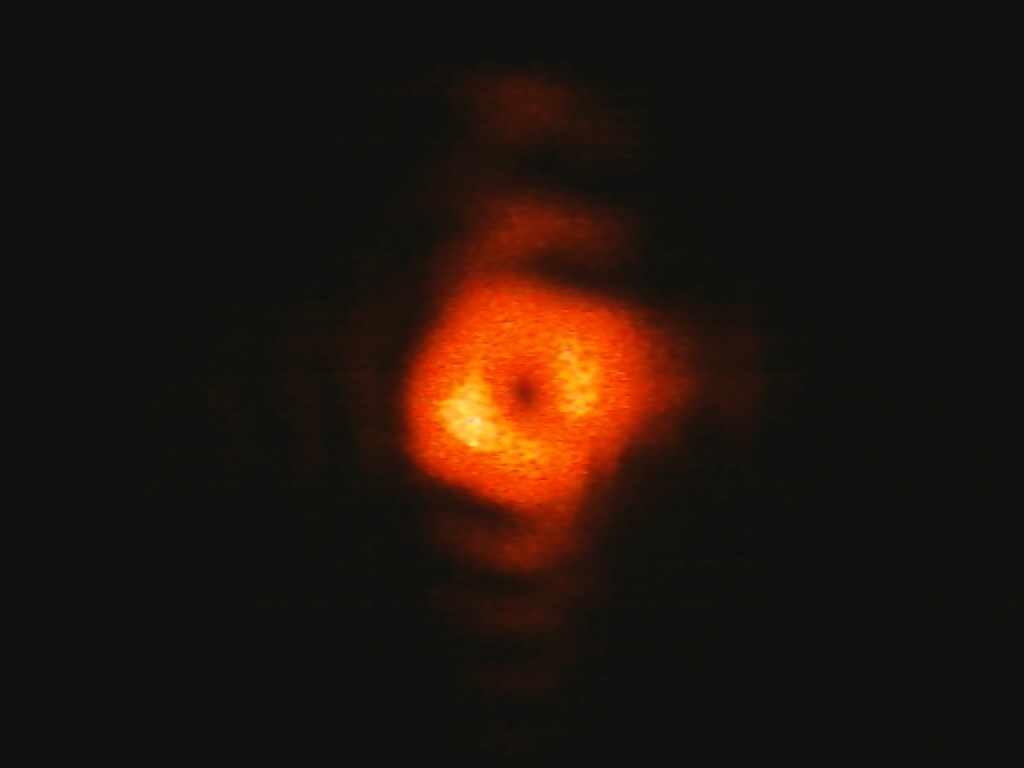
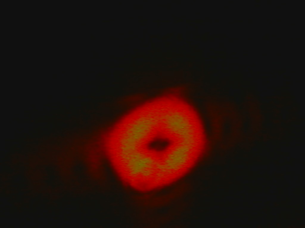
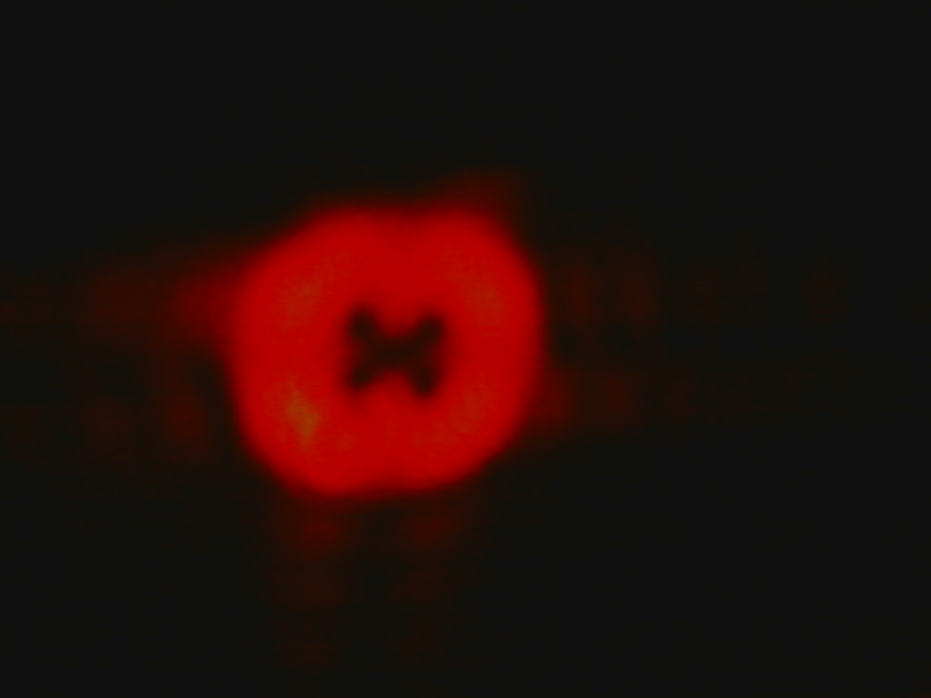
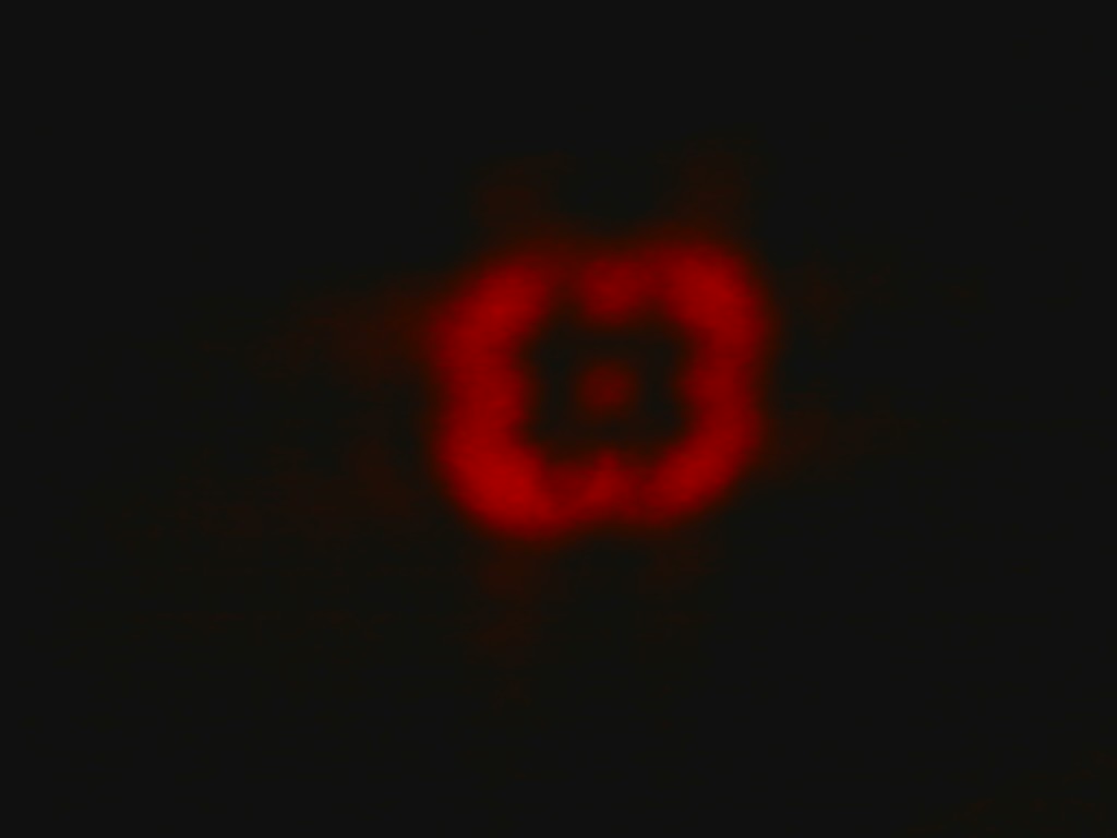
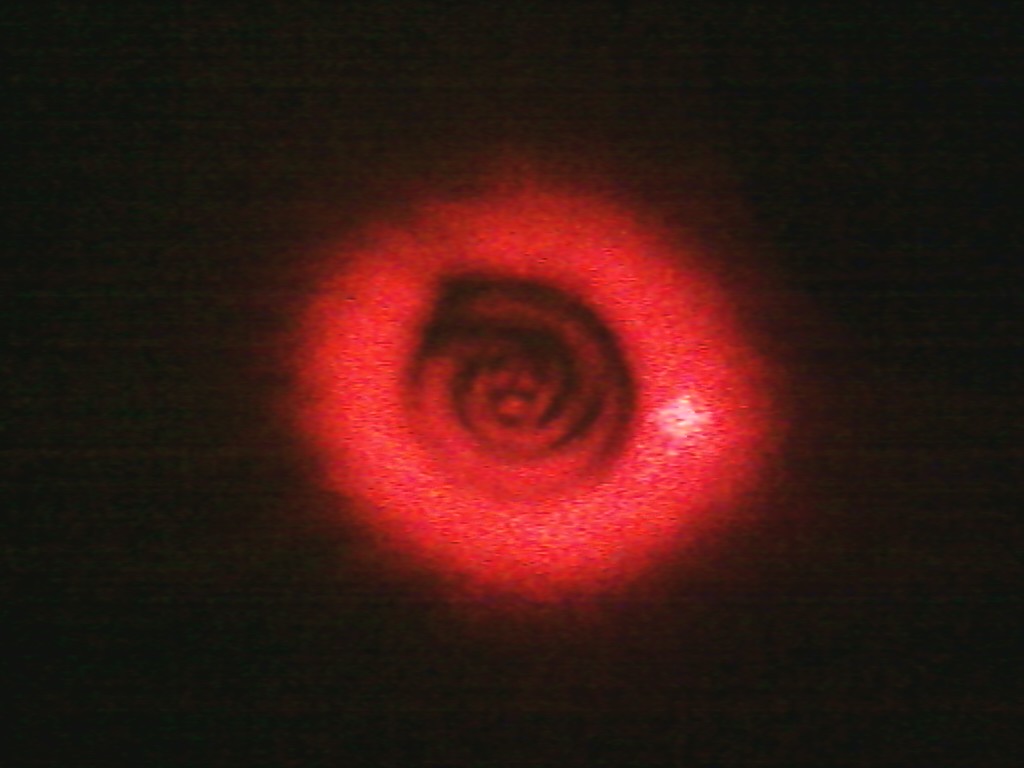
Below are pictures of HG modes I produced and converted to LG modes.
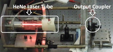
 HG 10 and LG 10
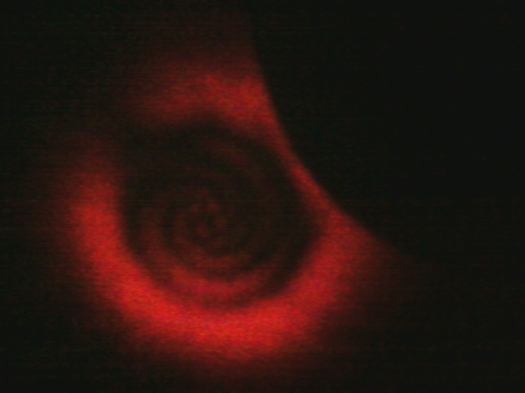
 HG 11 and LG 11
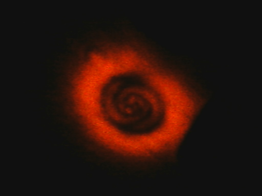
 HG 04 and LG 40
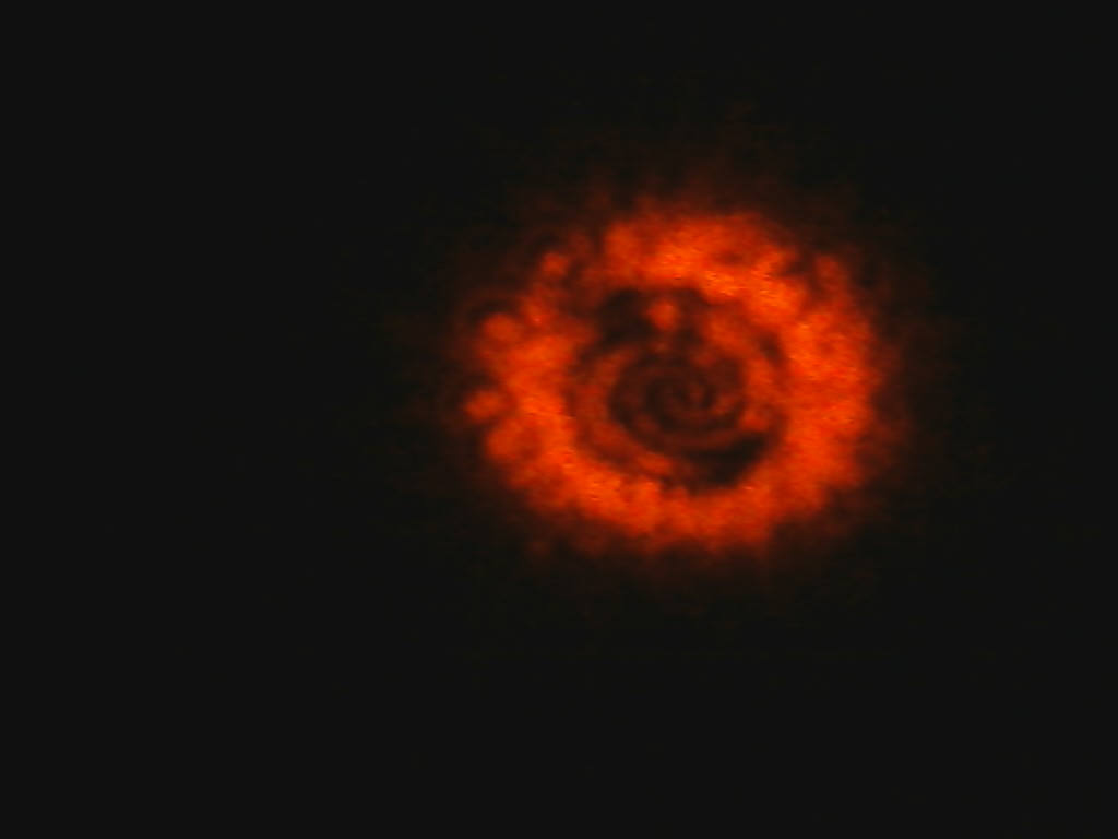
 HG 03 and LG 30
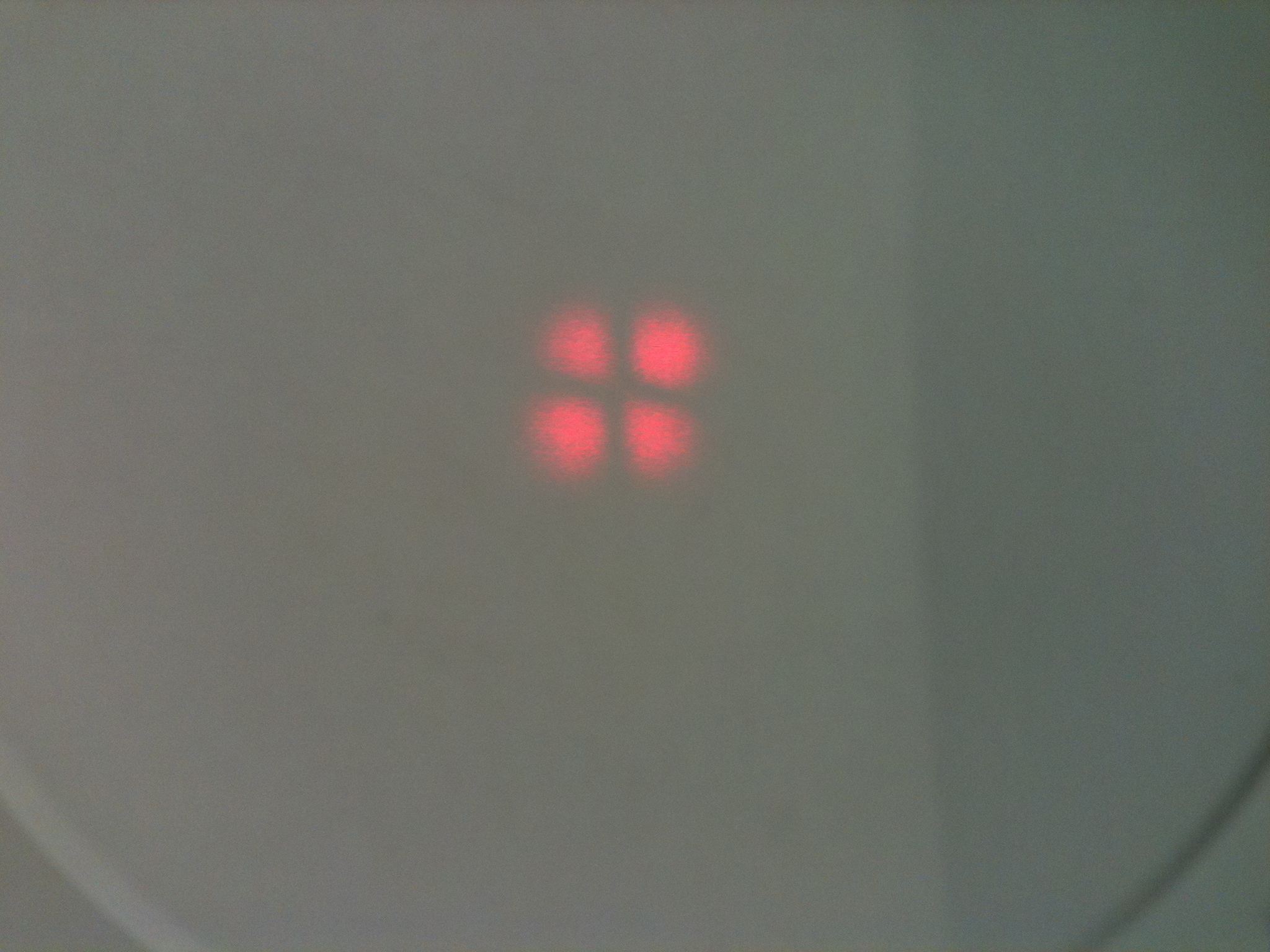
 HG 21 and LG 21
 HG 31 and LG 31
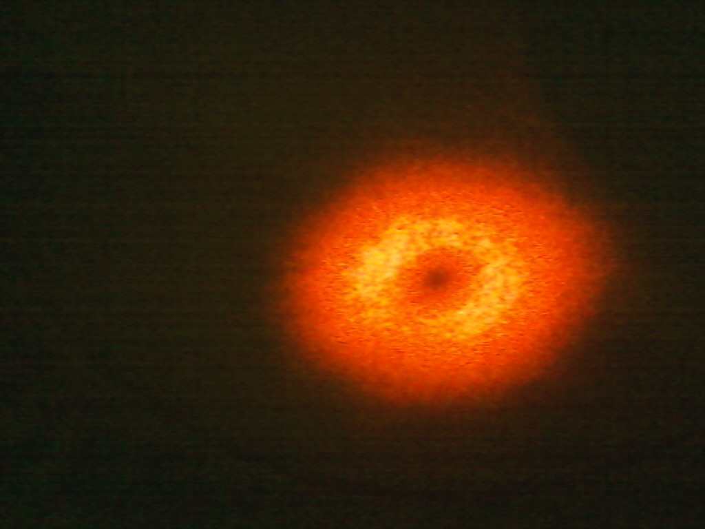
 HG 13
HG 13
For my experiment the relevant LG modes are the LG 10,20,30,& 40 modes since these are simple vortices whose topological charge is equal to the first index (e.g. LG20 has TC=2).
Data
d1=38 cm
d2=21 cm
f=40cm
ds=56.56cm
L=195.6 cm
Here d1 refers to the distance between the coupling window and the mode matching lens and d2 refers to the distance between the mode matching lens and the astigmatic mode converter. ds is the distance between the cylindrical lenses, f is the focal length of the cylindrical lenses, and L is the distance between the coupling window and the screen. These measurements will remain constant throughout the experiment except where otherwise noted.
Triangular Aperture
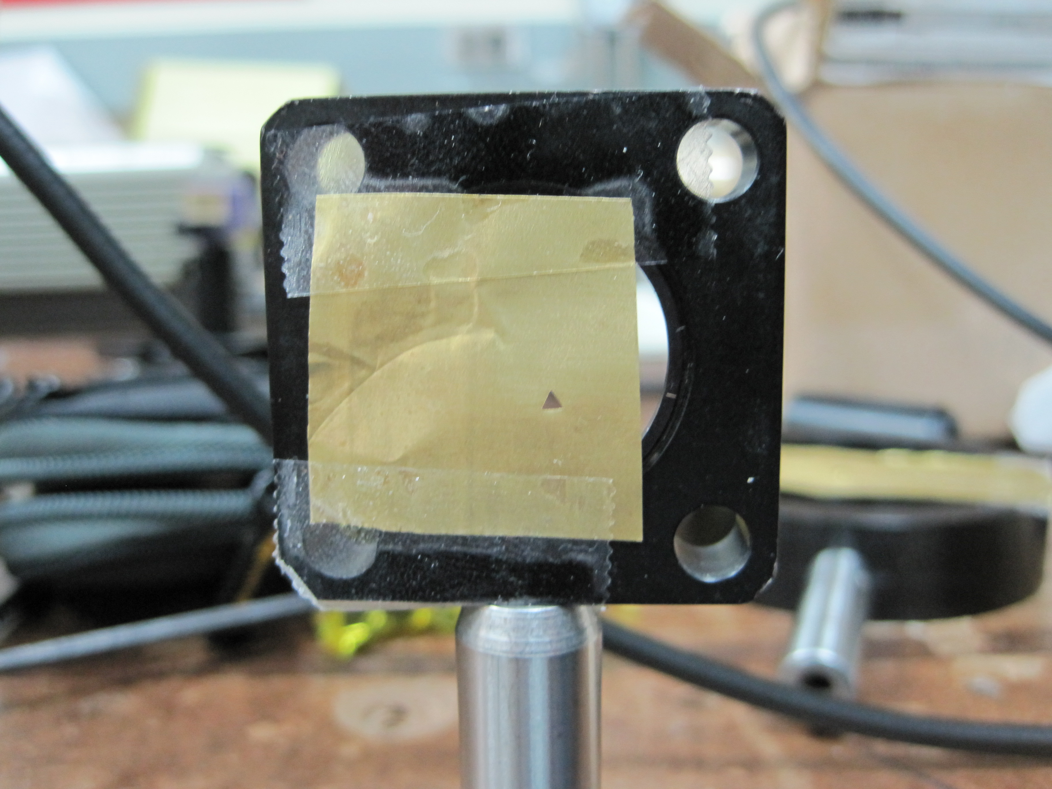
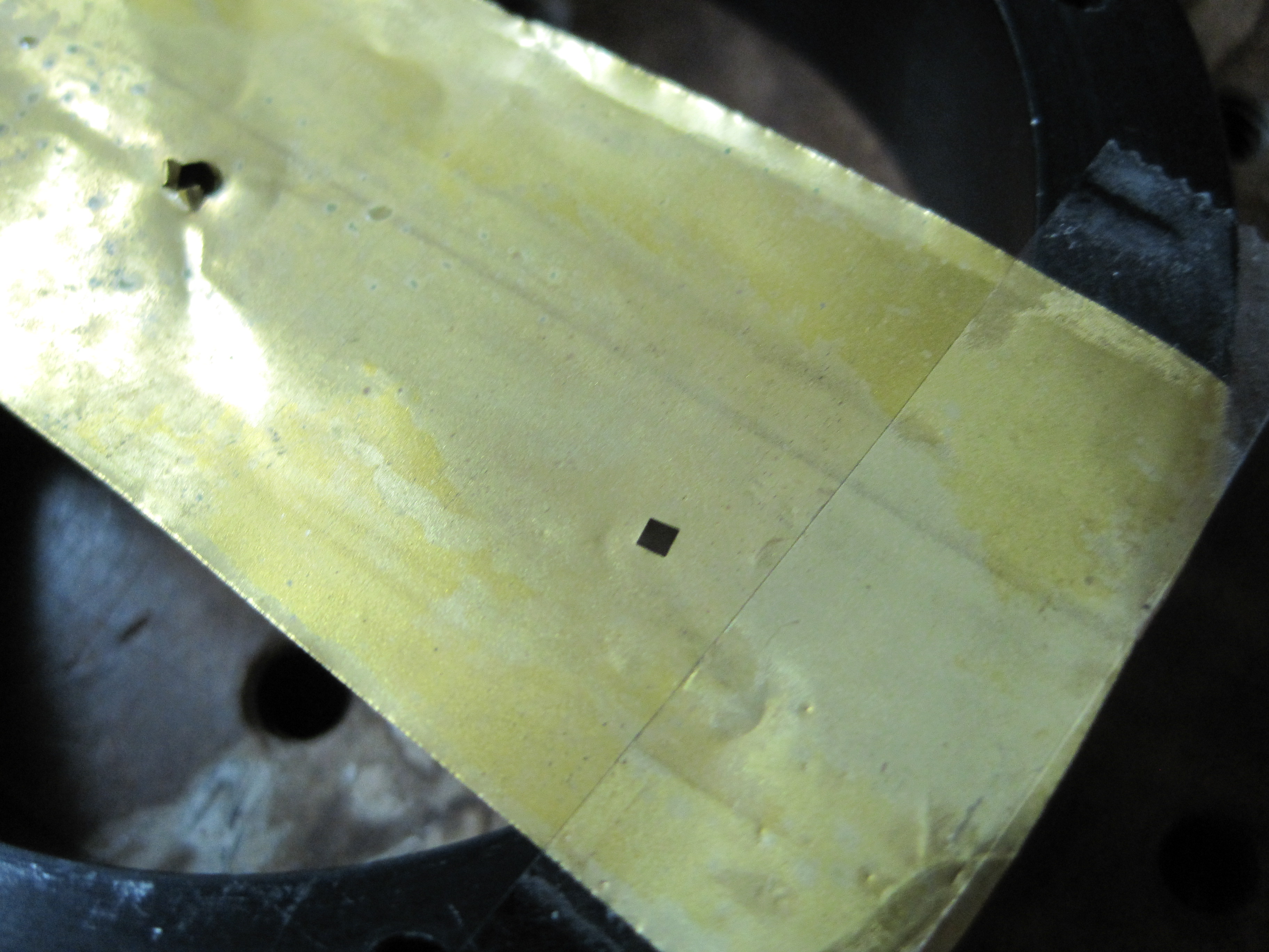
In this part of the experiment I attempted to recreate the results from the Hickmann paper using a triangular aperture. The aperture was made in the Advanced Technology Lab (ATL) using Electric Discharge Machining (EDM). In this set up two electrodes have a voltage put across them and they are repeatedly brought close so that current will flow, then brought apart to break the current, and then brought down again. This occurs multiple times while the electrodes are submersed in oil and eventually the bottom electrode will have an aperture cut into it in the shape of the top one. In this case the top electrode is a copper-tungsten powder metal and the bottom one is a sheet of brass. In my experiment I worked with an equilateral triangle with sides that were 1.7mm long.
Below are some pictures from when I shined certain LG beams on the triangular aperture.
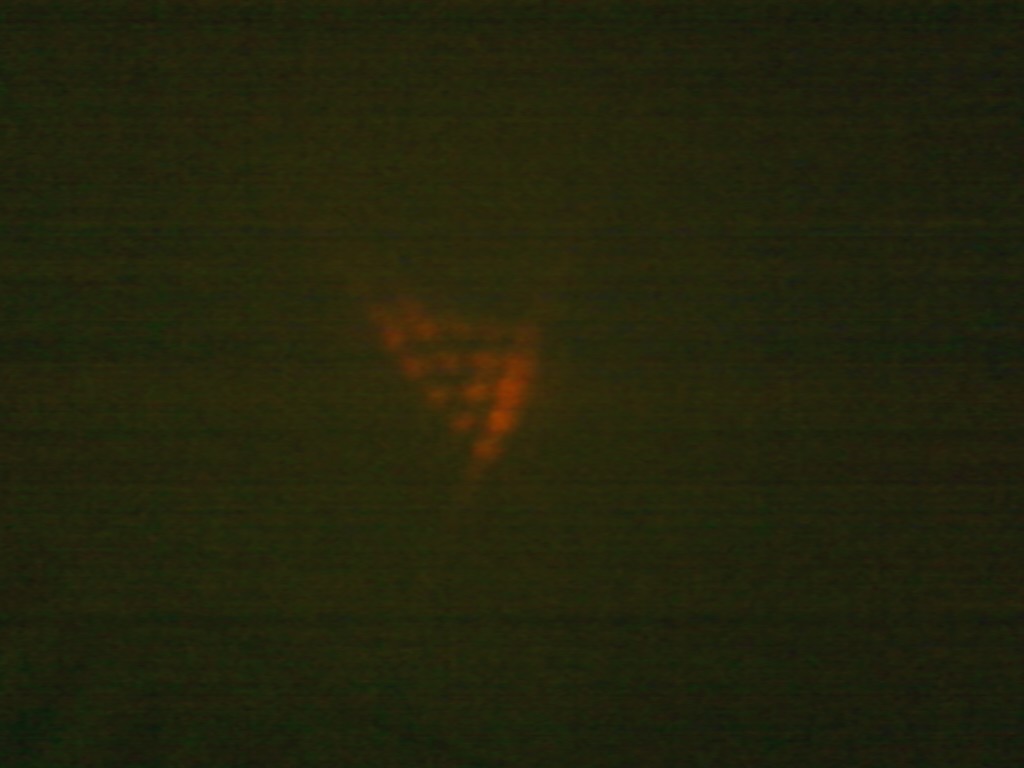
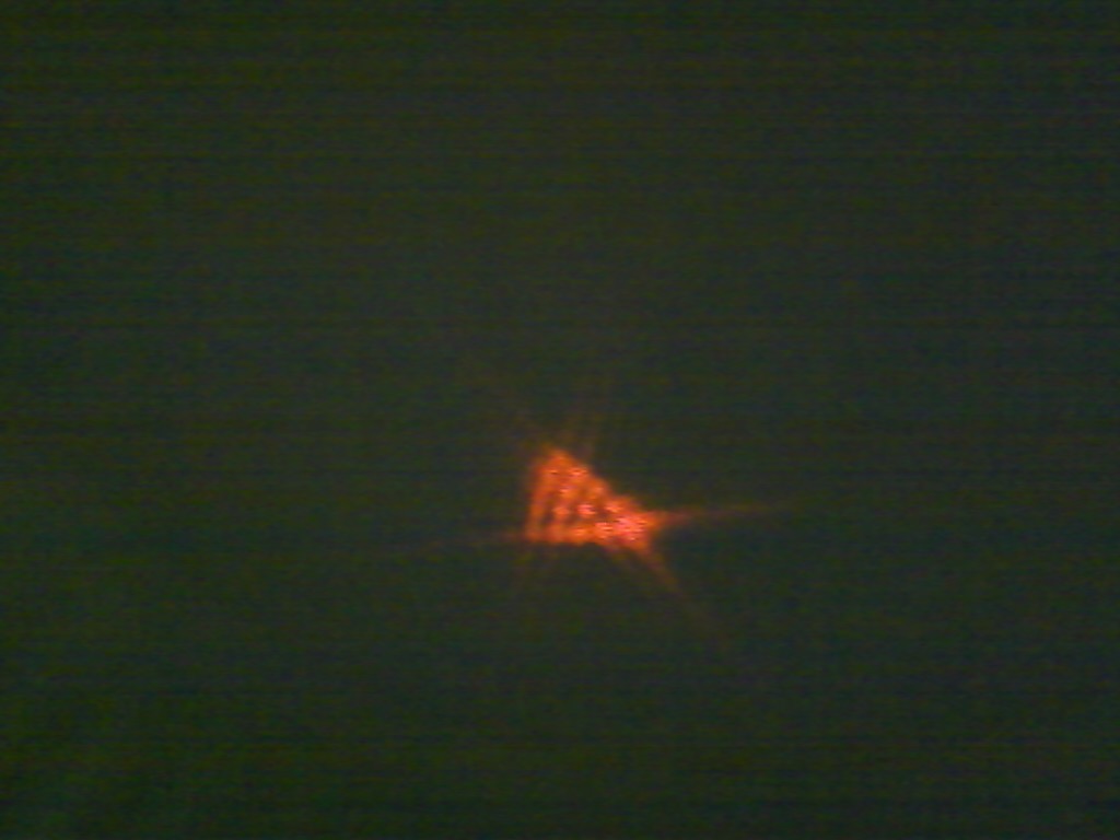
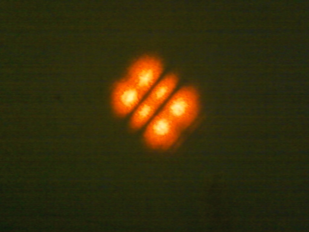
In these two pictures the incident beam is an LG 40 mode, and this can be seen by that fact the triangular lattice has 5 points for each side. We can also see how the sign of the topological charge comes into play. To reverse the charge of the beam I rotated the astigmatic mode converter by 45° and its effect can be seen in how the diffraction pattern reverses its orientation.
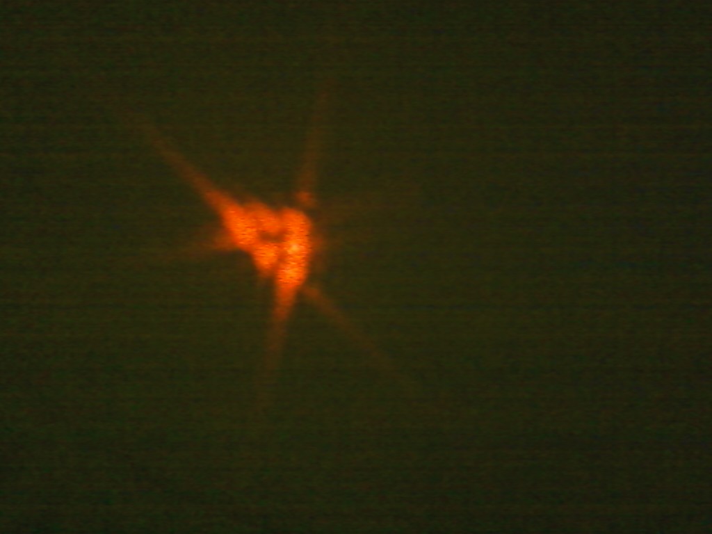
The following photo is the diffraction pattern for a triangular aperture when the incident beam is an LG 20 mode and once again the pattern holds up.
Data
x1=23.5cm
x2=17.5cm
f1=10cm f2=4cm
x1 is the distance between the astigmatic mode converter and the triangular aperture and x2 is the distance between the two focusing lenses. The first lens is placed right after the triangular aperture and the distance is about 2cm. f1 is the focus length of the lens place right after the aperture and f2 is the focus length of the second lens.
Rectangular Aperture
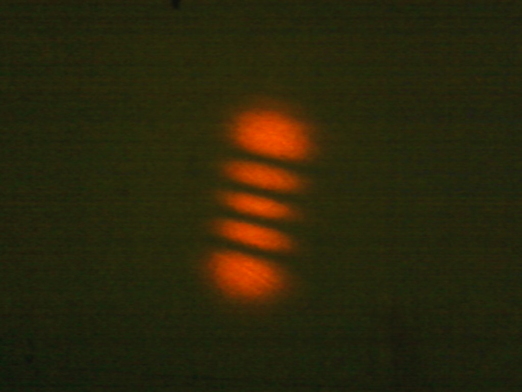
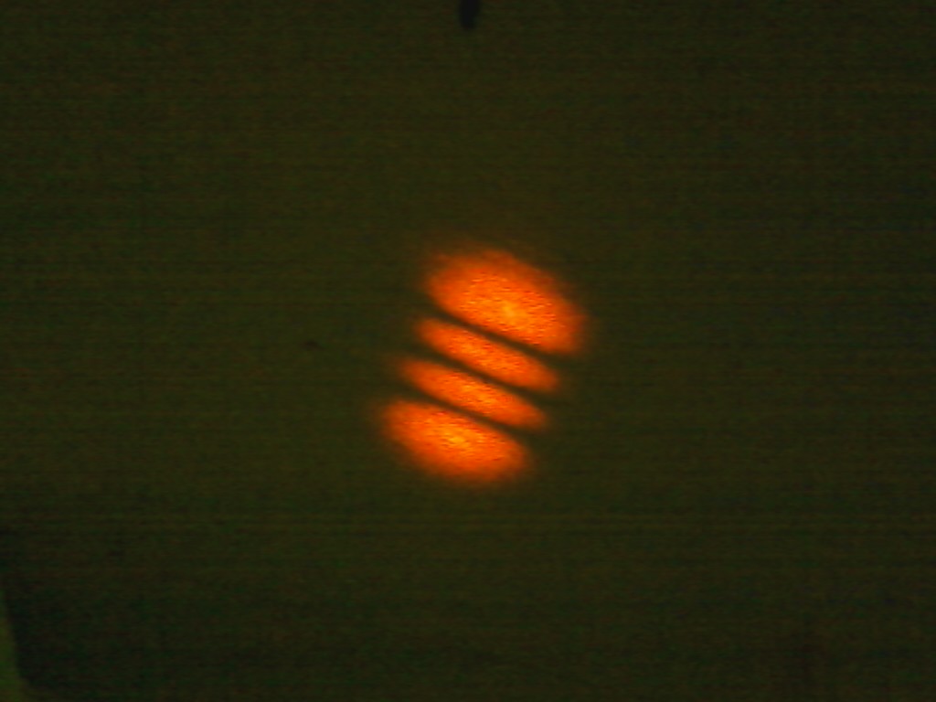
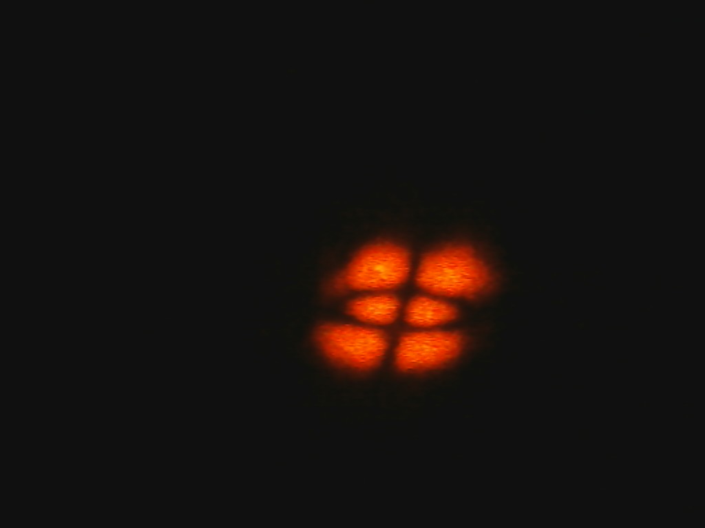
In this part of the experiment I worked with a rectangular aperture whose sides were each approximately 1.4mm. As can be seen in the pictures below, there is a clear relationship between the topological charge and the pattern, but it is not useful in terms of determining the charge from the pattern itself.
From left to right l=1,2,3,4.
Data
x3=30cm
x4=23cm
f3=12.5cm
f4=3.5cm
x3 refers to the distance between the mode converter and the rectangular aperture and x4 is the distance between the two lenses. Once again the first lens is placed right after the aperture and the distance between them is approximately 2cm. f3 is the focal length of the lens placed after the aperture and f4 is the focal length of the second aperture.
Circular Aperture
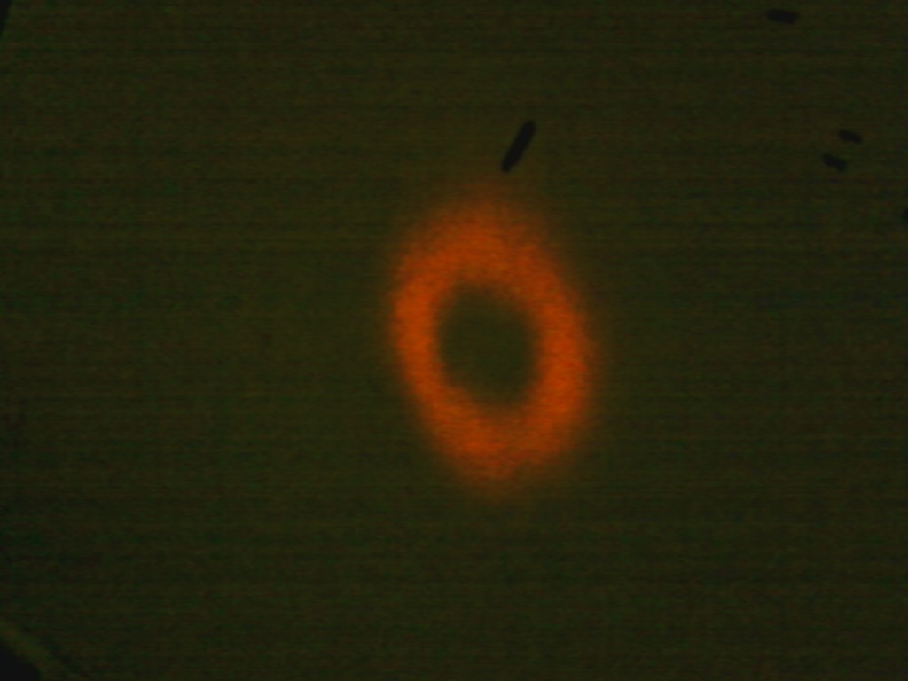
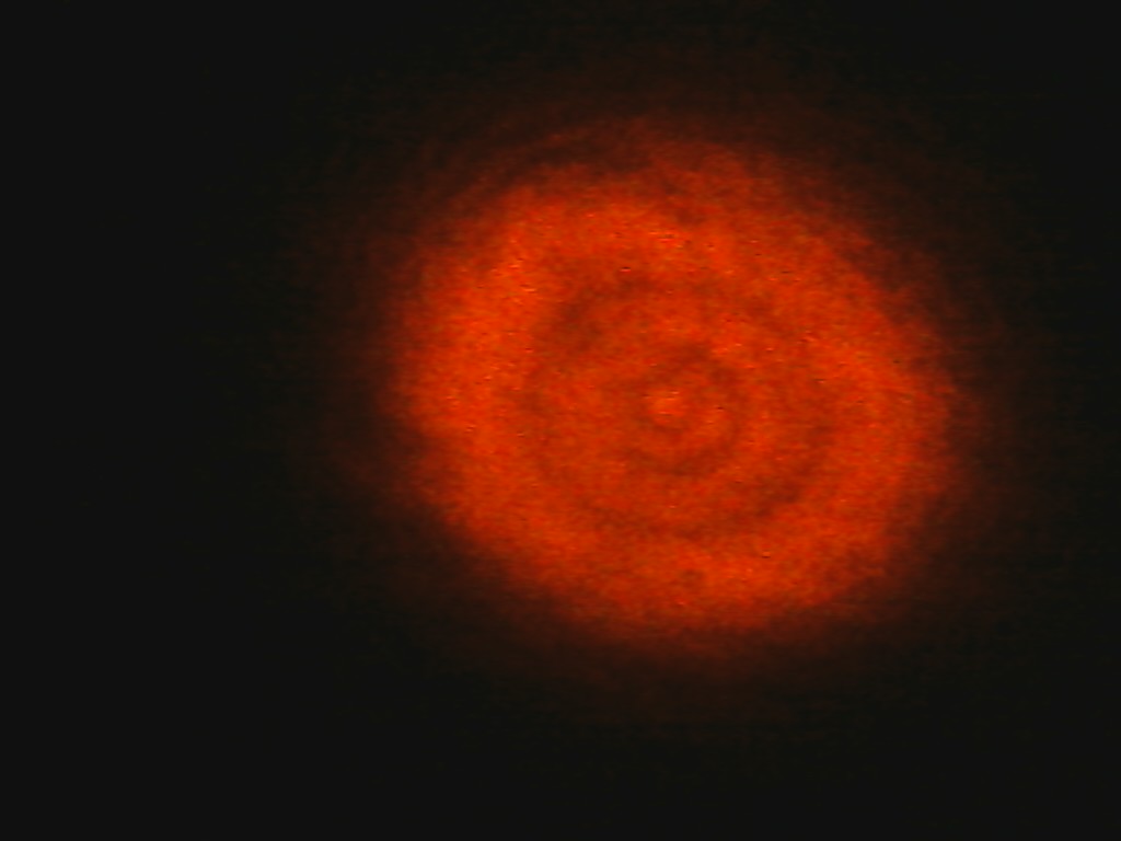
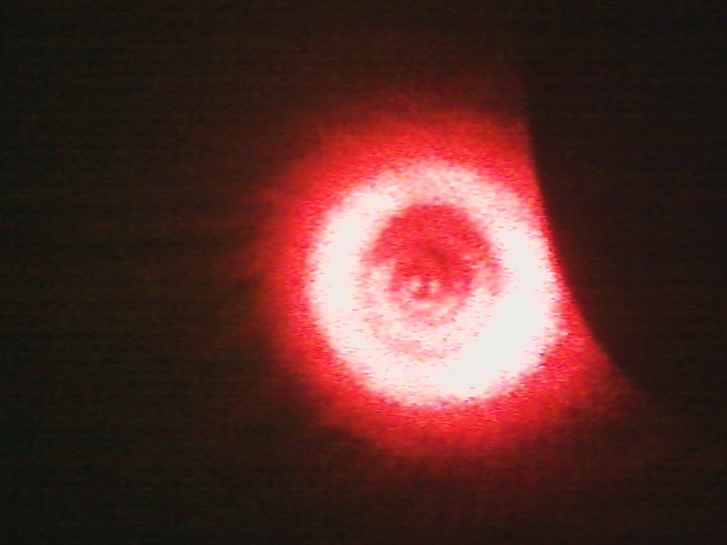
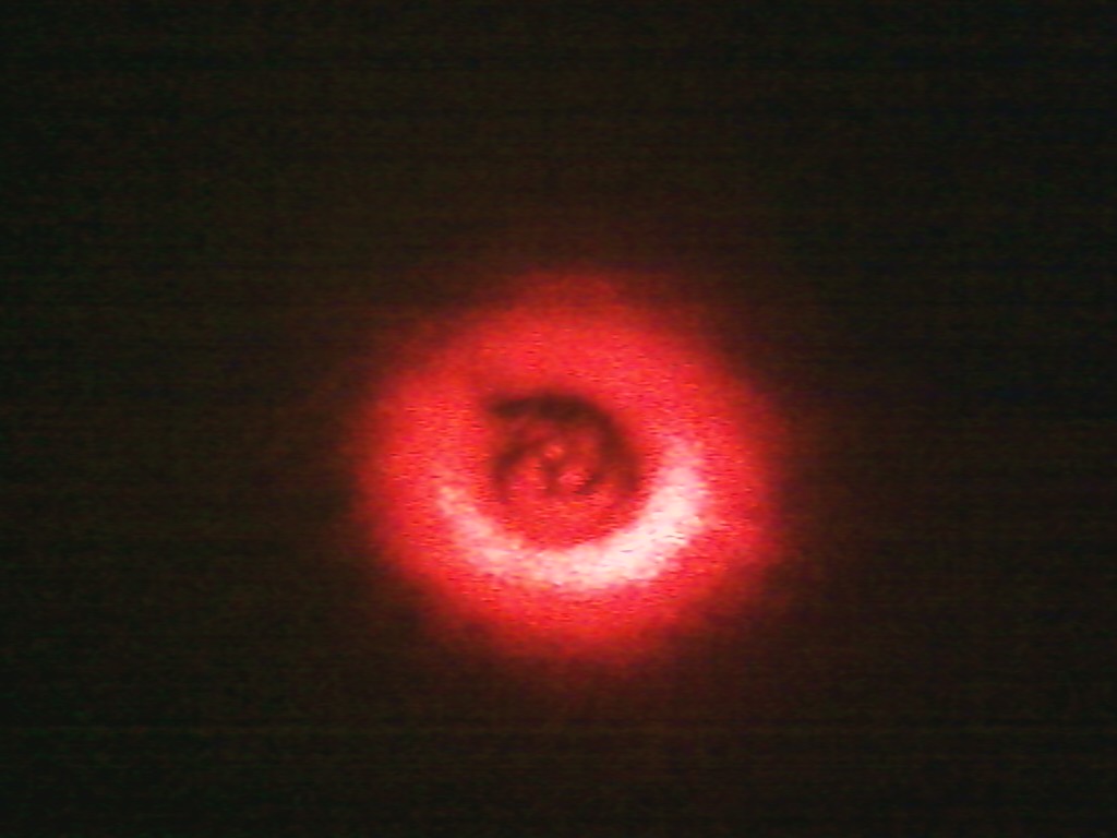
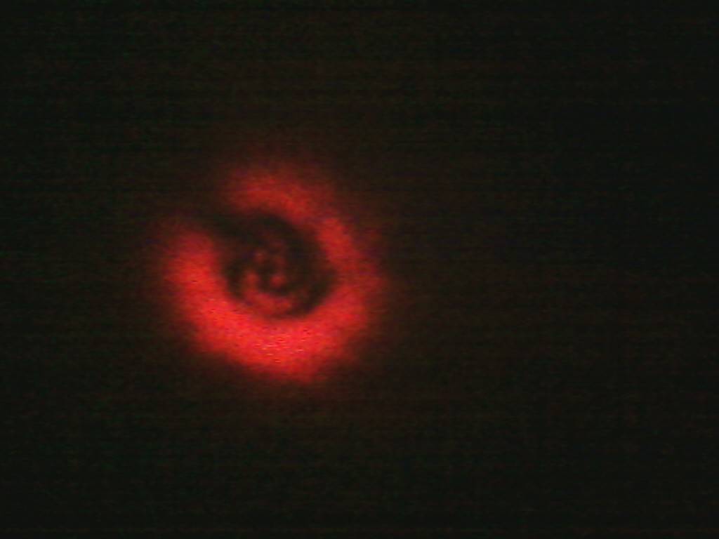
In this part I worked with a 1000 micron diameter circular aperture. Here the important results did not deal with the usual far field diffraction pattern for an optical vortex diffracted by a circular aperture. Ways to measure the absolute value of the topological charge using a circular aperture has been well documented. In my experiment I obtained a diffraction pattern that gave information on both the absolute value and sign of the topological charge. I used two different set ups to obtain the given pattern.
Setup 1
-The first lens (f5) is placed right after the 1000 micron circular aperture so the distance between them is 2cm.
f5=12.5cm
f6=3.5cm
-The second lens was then moved from 1 inch away from the first lens to 3.5 inches (~2.5cm to ~9cm). As the lens was moved the pattern would rotate about the center, while the center core of the pattern was determined by the absolute value of the topological charge.
Setup 2
-In this setup I only kept the first lens and that was moved instead. The first lens was moved over a range of right after the aperture (~2cm) to approximately its focal length away from the aperture, ie the aperture was in the front focal plane of the lens so a image of the aperture was projected onto the screen).
-Both of these setups gave equivalent results, but the first was advantageous since the image projected onto the screen was larger and clearer.
 l=1,2
l=1,2
 l=3,4
l=3,4
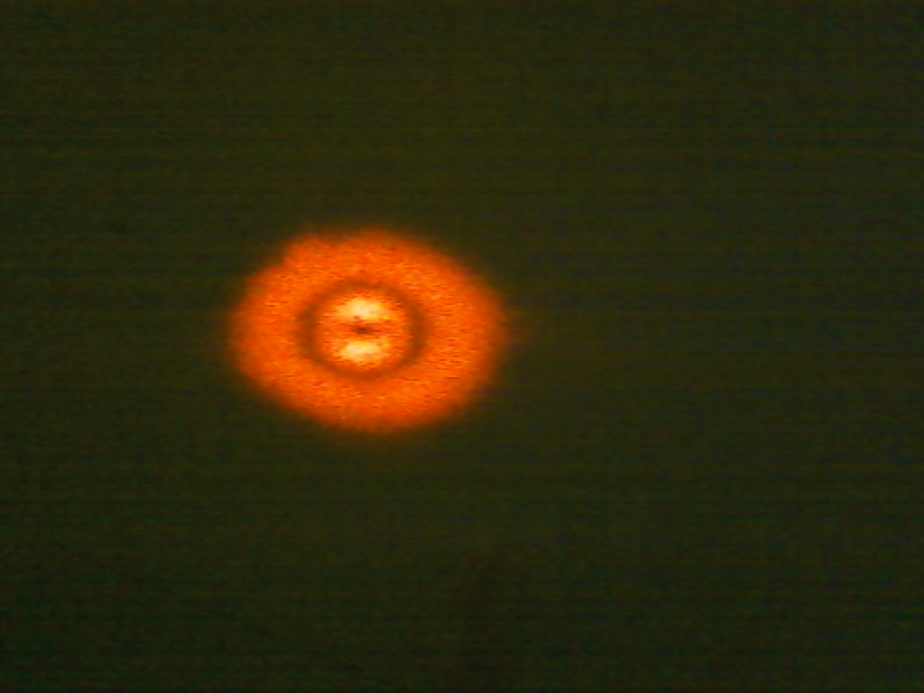
As can be seen, the number of the points in the center of the pattern corresponds to the absolute value of the charge.
As mentioned before, in setup 1, as the second lens was moved, the diffraction pattern would rotate about its center (with more lines spiraling around the center). This can be seen in the following pictures.
The important question is what this information can tell us about the sign of the topological charge. When I reversed the sign of the charge by rotating the astigmatic mode converter by 45° I saw that the orientation of the rotation would reverse. If the pattern would rotate counterclockwise when brought forward with a given charge, it would rotate clockwise when the charge was reversed. However, in some cases this is not necessary and the sign of the charge can be determined without having to move lenses. Below it can be seen that by changing the sign of the topological charge, the spiral pattern is reversed.
This method does have its limitations. For example, if the topological charge has an absolute value of 1, a spiral pattern isn't visible and the core will not rotate but change between a dark and bright spot.
Another interesting relation was noted in how the pattern would rotate the the topological charge of the beam. It was observed that the speed of the rotation was inversely proportional to the charge.
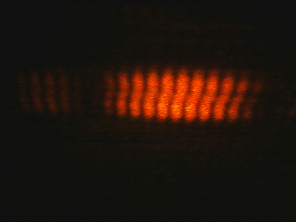
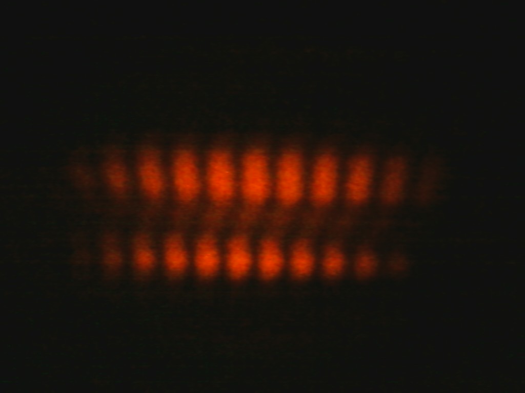
Double Slit
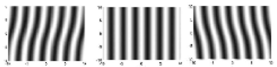 TC=1,0,-1
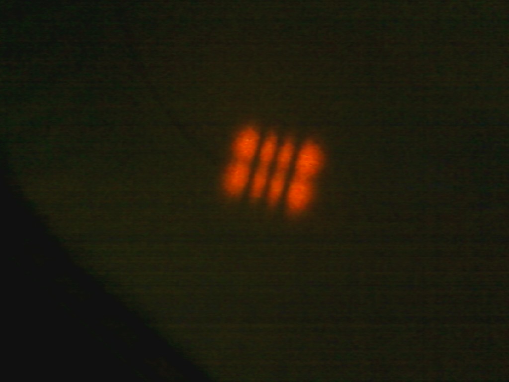
In 2006 H.I. Sztul and R.R. Alfano demonstrated how using the double slit interference pattern could distinguish between beams of opposite charge. When the charge was reversed, the orientation of the pattern was reversed. [4]
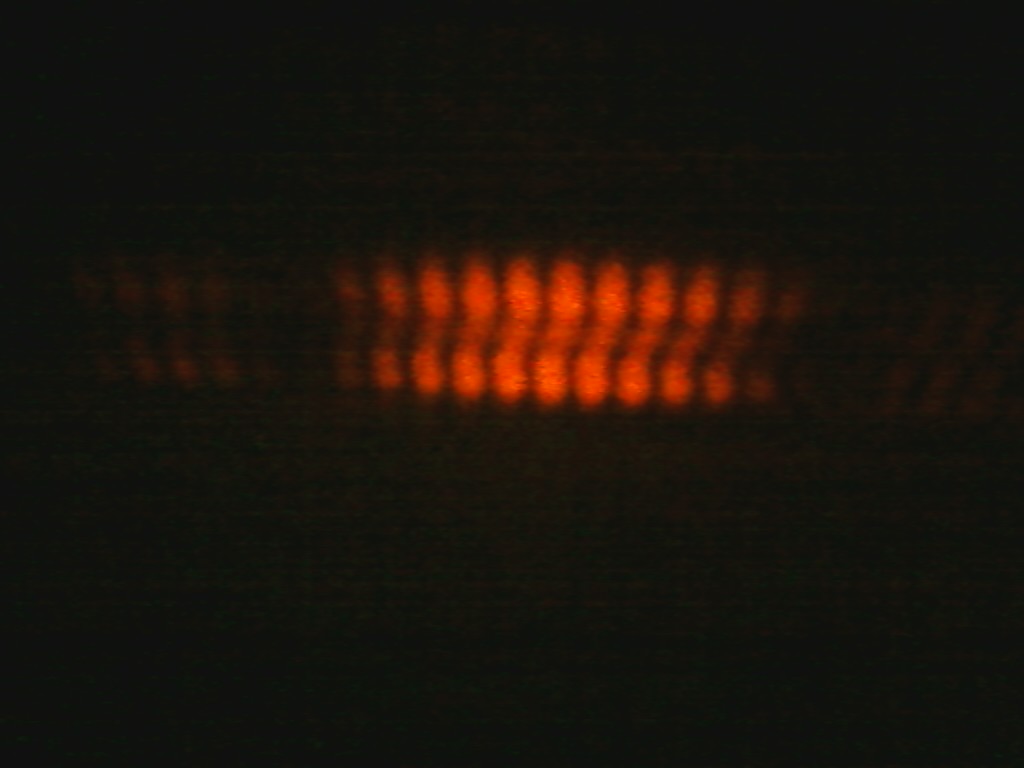
TC=1,2,3
It can be seen that the pattern does change as the topological charge is increased. The slope of the tilt becomes larger and more noticeable and the middle horizontal band becomes dimmer. However, this setup seems more suited for determining the sign of the charge as opposed to the absolute value.
Analysis and Conclusion
Using their diffractive properties, we have seen a clear relationship between the diffraction pattern and the topological charge of a vortex beam. With the triangular aperture we have been able to reproduce the previous experiments done by Hickmann et al. We were also able to see how the absolute value of the charge affected the diffraction pattern for a rectangular aperture. For the double slit experiment we were able to extend the work of H.I. Sztul and R.R. Alfano by seeing how the double slit interference pattern was affected by higher charges. With the circular aperture we were able to see a pattern that gave information on both the absolute value and sign of the charge that was not the usual far field diffraction pattern. Overall this project has shown the important relationship between a vortex's diffractive properties and its azimuthal phase dependence, along with pointing to other areas for future study.
Acknowledgements
This work was supported by the National Science Foundation (PHY-0851594).
I'd like to thank Pete Davis for his invaluable help in creating the rectangular and triangular apertures.
References
[1] M.W. Beijersbergen et al., Optics Communications 96 , 123-132 (1993)
[2] Monroe, Don. "Triangular Hole Reveals Light's Rotation." Physical Review Focus. Physical Review, 30 July 2010. Web. 31 July 2011.
[3] J.M. Hickmann et al., Phys. Rev. Lett. 105, 053904 (2010)
[4] H.I. Sztul et al., Optics Letters 31, Issue 7, 999-1001 (2006)
[5] L. Allen et al., Phys. Rev. A 45, 8185-8189 (1992)
[6] "Gaussian Beam." Wikipedia. 26 July 2011. 31 July 2011. http://en.wikipedia.org/wiki/Gaussian_beam
[7] "Hermite Gaussian Modes." Encylopedia of Laser Physics and Technology. 16 February 2011. 31 July 2011. http://www.rp-photonics.com/hermite_gaussian_modes.html
[8] Weisstein, Eric W. "Hermite Polynomial." Wolfram MathWorld. 2011. 31 July 2011. http://mathworld.wolfram.com/HermitePolynomial.html
[9] Padgett, Miles. "Orbital Angular Momentum of Photons." University of Glasglow Optics Group. 31 July 2011. http://www.physics.gla.ac.uk/Optics/play/photonOAM/
[10] "Light With Orbital Angular Momentum." American Institute of Physics. 31 July 2011. http://www.aip.org/png/2005/229.htm
[11] Gregoric, Vince. "A Precise Measurement of the Speed of Light in Air from the Separation of Longitudinal Modes in an open-cavity HeNe Laser," Laser Teaching Center. June 2010. 31 July 2011. http://laser.physics.sunysb.edu/~vince/report/report.html