Creating Circularly-Polarized Light with a
Readily-available Birefringent Polymer
Azure Hansen, John Noé, Harold Metcalf
Laser Teaching Center
Department of Physics & Astronomy
Stony Brook University
The immediate motivation for this project was the need to create circularly polarized light in the near-infrared (780 nm) for use in a device to lock the frequency of a diode laser to atomic transitions in rubidium. Commercial waveplates are available for this purpose, but they typically cost many hundreds of dollars and must be purchased for specific wavelengths. We demonstrate that it's possible to create useful waveplates for any desired wavelength simply by suitably orienting a thin sheet of the readily-available birefringent polymer cellophane with respect to the incident beam of light.
Waveplates (also called retarders) create a phase shift between
orthogonal components Ex and
Ey of the electric field vector E;
birefringent materials are used because they have different indices of
refraction for different components of E. Circularly polarized
light results if Ex and
Ey have equal magnitude and differ in phase
by exactly π/2, or 90 degrees. Other waveplates with a π phase
shift are very useful for changing the orientation of polarized
light. The retardance (phase shift in radians) of a birefringent
material is given by
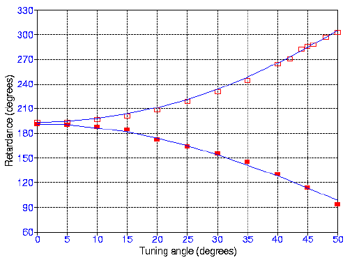
The figure below summarizes our experiment. The light source was a
HeNe laser (633 nm) linearly polarized at 45° to the horizontal. A
cellophane sample obtained from a local florist was mounted on a
rotator (horizontal rotation axis) which sat on a small horizontal
turntable (vertical axis). The tuning angle is the rotation about the
vertical axis, which can be set with the upper rotator to coincide
with either the o-axis of the cellophane (solid points on the graph)
or the e-axis (open points).
Retardances were determined through the relationship